Grundfos DMH 25 Series Installation And Operating Instructions Manual
Dosing pump
Hide thumbs
Also See for DMH 25 Series:

Related Manuals for Grundfos DMH 25 Series


Summary of Contents for Grundfos DMH 25 Series
-
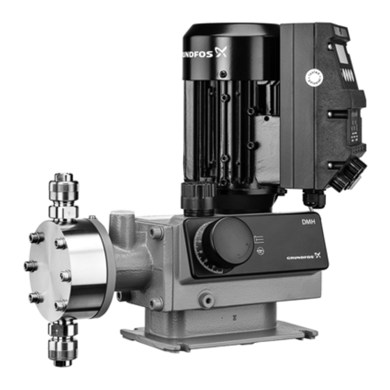
Page 1: Installation And Operating Instructions
GRUNDFOS INSTRUCTIONS DMH 25X Dosing pump Installation and operating instructions Further languages http://net.grundfos.com/qr/i/96771725... -
Page 2: Table Of Contents
Intermediate storage nearest Grundfos company. Return Product description and accessories 1.2 Service documentation General description If you have any questions, please contact the nearest Grundfos Dimensional sketches company or service workshop. Weight Stroke volume 1.3 Applications Materials... -
Page 3: Safety
The pump housing, control unit and sensors must damages may be lost. only be opened by personnel authorised by Grundfos! Non-observance of the safety instructions may lead to the following hazards: Repairs must only be carried out by authorised and qualified personnel! •... -
Page 4: Unauthorised Modification And Manufacture Of Spare Parts
2.7 Unauthorised modification and manufacture of 3. Technical data spare parts 3.1 Identification Modification or changes to the pump are only permitted following agreement with the manufacturer. Original spare parts and accessories authorised by the manufacturer are safe to use. Using other parts can result in liability for any resulting consequences. -
Page 5: Type Key
3.2 Type key Example: DMH 220-10 B-PVC/V/G-X-E1B8B8 Code Description Remark Type Hydraulic piston diaphragm dosing pump Maximum flow 220 l/h maximum capacity of the pump Example Maximum pressure Maximum counterpressure 10 bar Example Single-head Number of dosing heads Double-head Standard (manual control) Stroke counter NAMUR, NC output AR control unit (analog / pulse control) AR control unit, with servomotor... - Page 6 Code Description Remark Standard valves (inlet and outlet valve not spring-loaded) Spring-loaded valves (inlet valve: 0.05 bar, outlet valve: 0.8 bar) Valve type Spring-loaded outlet valve (0.8 bar), standard inlet valve (not spring-loaded) Valves for abrasive media Larger inlet valve (not spring-loaded) G 5/8 - hose 6/12 mm and pipe cementing ∅12 mm (PVC) G 5/8 - pipe threaded Rp 1/4 female (SS) G 5/8 - pipe welding ∅16 (PP, PVDF)
-
Page 7: Pump Types
3.3 Pump types The DMH 25X dosing pump is available for a variety of performance ranges in various sizes. Pump type and designation, see pump nameplate. The following is indicated on the pump nameplate (see section Identification): • The pump type which specifies the stroke volume, connection size and performance data (see below). - Page 8 Pump type 50 Hz 60 Hz 100 Hz Max. Max. Max. p max. stroke p max. stroke p max. stroke Single pump Double pump rate rate rate [l/h] [bar] [n/min] [l/h] [bar] [n/min] [l/h] [bar] [n/min] DMH 254 DMH 50-10 DMH 50-10/50-10 DMH 102-10 DMH 102-10/102-10...
- Page 9 Maximum counter-pressure* Pump type p max. Pump type [bar] Single pump Double pump p max. [bar] Single pump Double pump DMH 257 DMH 251 DMH 220-10 DMH 220-10/220-10 DMH 440-10 DMH 440-10/440-10 DMH 2.4-10 DMH 2.4-10/2.4-10 DMH 575-10 DMH 575-10/575-10 DMH 5-10 DMH 5-10/5-10 DMH 750-4...
-
Page 10: Sound Pressure Level
(stores a maximum of 65,000 pulses) ≤ T ≤ 40 °C • two-stage tank-empty signal (e.g. via Grundfos tank empty • Permissible ambient temperature: 0 °C (standard) to +40 °C sensor) (for an installation height up to 1000 m above sea level) •... -
Page 11: Dosing Medium
[°C] [°C] [°C] as contaminated. If Grundfos Water Treatment is requested to service the pump, it Stainless steel, must be ensured that the pump is free from substances that can DIN 1.4571* be injurious to health or toxic. If the pump has been used for such substances, the pump must be cleaned before it is returned. -
Page 12: Product Description And Accessories
5. Product description and accessories 5.1 General description The DMH 25X are oscillatory positive-displacement pumps with The hydraulic excursion of the solid PTFE diaphragm (Q) hydraulic diaphragm control. The operation procedure of the displaces an equivalent volume of dosing medium from the dosing pump is shown in the sectional drawing. - Page 13 Fig. 4 DMH 254 Fig. 5 DMH 255...
- Page 14 Fig. 6 DMH 257 Pos. Components Motor Worm gearing Eccentric Recuperating spring (not with drive size 3) Sliding plug Piston Crank Combined overpressure and degassing valve Degassing valve Diaphragm protection system (AMS) Dosing diaphragm Dosing head Suction valve Discharge valve Stroke-length adjustment knob Oil-filling screw with dipstick 5.1.1 Combined overpressure and degassing valve...
- Page 15 5.1.3 Double-diaphragm system/diaphragm leakage Functional principle of diaphragm leakage detection detection (optional) The non-return valve and the gap between the diaphragms are factory-filled with a separating agent (paraffin oil). They are set in General such a way during start-up on the test stand that there is always a The piston diaphragm and high-tech dosing pumps with drift-free hydraulically separated equilibrium between the valve and diaphragm leakage detection are equipped with the following:...
-
Page 16: Dimensional Sketches
5.2 Dimensional sketches 5.2.1 DMH 251, 252, 253 ∅ 9mm Fig. 8 DMH 251, 252, 253 Pos. Description For double pump, motor turned by 180 ° Pump type DMH 251 DMH 252 DMH 253 Measurements in mm. - Page 17 5.2.2 DMH 254, 255, 257 ∅ 9mm Fig. 9 DMH 254, 255, 257 Pos. Description For double pump, motor turned by 180 ° fx, mx For double pumps Pump type DMH 254 DMH 255 DMH 257 Measurements in mm.
-
Page 18: Weight
5.3 Weight 5.6 Data of contact pressure gauge for diaphragm leakage detection (optional) Weight [kg] Following data is not valid for contact pressure Dosing head Pump type Note Single Double gauges in explosion-proof version. material pump pump The contact pressure gauge has a reed switch with electrically isolated contact output, maximum switching power 10 W for DC PVC, PP, PVDF current or 10 VA for AC current. -
Page 19: Approximate Values When Using Pulsation Dampers
6.4 Approximate values when using pulsation Maximum dampers Nominal Stroke rate length of Pump type width of [n/min] suction line Risk of damage to the system! suction line It is always recommended to use pulsation dampers for large high-speed pumps! DMH 254 In particular for pump types with a flow rate above DMH 50-10... -
Page 20: Optimum Installation
6.5 Optimum installation Max. 1 m max. 1m Fig. 10 Example of optimum installation Pos. Components Dosing tank Electric agitator Extraction device Suction pulsation damper Dosing pump Relief valve Pressure-loading valve Pulsation damper Measuring glass Injection unit... -
Page 21: Installation Tips
6.6 Installation tips • For easy deaeration of the dosing head, install a ball valve (11i) with bypass line (back to the dosing tank) immediately after the discharge valve. • In the case of long discharge lines, install a non-return valve (12i) in the discharge line. -
Page 22: Tube / Pipe Lines
With open outflow of the dosing medium or a 6.8 Connecting the suction and discharge lines counter-pressure below 2 bar Warning • Install a pressure-loading valve (7i) immediately before the outlet or the injection unit. All lines must be free from strain! A positive pressure difference of at least 2 bar must be ensured Only use the prescribed line types! between the counter-pressure at the injection point and the... -
Page 23: Electrical Connections
Observe the local safety regulations! The pump housing must only be opened by personnel authorised by Grundfos! Protect the cable connections and plugs against corrosion and humidity. Only remove the protective caps from the sockets Fig. -
Page 24: Connecting The Power Supply Cable
Note The pump housing must only be opened by (indicated by an arrow on the valve)! personnel authorised by Grundfos! Repairs must only be carried out by authorised and qualified personnel! Observe the flow direction of valves (indicated by an... -
Page 25: Start-Up/Subsequent Start-Up Of Dmh 251, 252 And 253
4. Let the pump run for approx. 5 minutes. oil, if necessary. 5. Check the oil level. Only use original Grundfos gear oil! Note – Set the stroke-length adjustment knob (L) to 40 %. For product numbers, see "Service kit catalogue" on –... -
Page 26: Setting The Pressure Relief Valve
Note Immersion depth to marking: approx. 5 mm. Check the oil level at least every two weeks and add oil, if necessary. Only use original Grundfos gear oil! Note For product numbers, see "Service kit catalogue" on www.grundfos.com Pump type... -
Page 27: Zero Point Adjustments
8.5 Zero point adjustments 8. Set the scale ring (4l) to zero. – Loosen the screw (3l) in the scale ring (4l) slightly using an 8.5.1 Adjusting the zero point for system pressures up to 100 hexagon key, M3. – Turn the scale ring (4l) until both "0" are the same on the The zero point of the dosing pump is factory-set to a slightly lower scale and scale ring. -
Page 28: Operation
Wear protective clothing (gloves and goggles) when working on the dosing head, connections or lines! The pump housing must only be opened by personnel authorised by Grundfos! Repairs must only be carried out by authorised and qualified personnel! Switch off the pump and disconnect it from the power... -
Page 29: Cleaning And Maintenance Intervals
10.3 Cleaning and maintenance intervals Checking the oil level • Check the oil level every two weeks and add oil, if necessary. Cleaning the valves • At least every 12 months or after 4,000 operating hours. • If the pump does not perform. •... -
Page 30: Replacing The Diaphragm And Gear Oil For Dosing Head With Single Diaphragm (No Diaphragm Leakage Detection)
10.6.3 Replacing a single diaphragm (no diaphragm leakage a drip tray by carefully unscrewing the suction valve. detection) Only use original Grundfos gear oil! • Remove the diaphragm and fit a new diaphragm (Q) on the suction side. See fig. 38. -
Page 31: Replacing The Diaphragm For Dosing Head With Double Diaphragm
Pos. Components Only use original Grundfos gear oil! Note For product numbers, see "Service kit catalogue" on Contact pressure gauge (installation position) www.grundfos.com... - Page 32 For product numbers of double-diaphragm filling 10.7.3 Fitting the dosing head Note components, see "Service kit catalogue" on • Fit the dosing head and cross-tighten the dosing head screws www.grundfos.com using a torque wrench. 10.7.5 Filling with gear oil See section 8. Start-up/shutdown for subsequent...
- Page 33 10.7.7 Cleaning the ball non-return valve Cleaning the ball non-return valve Only clean the ball non-return valve after a Note diaphragm breakage! Fig. 42 Contact pressure gauge Fig. 43 Ball non-return valve Pos. Components Contact pressure gauge Pos. Components Union nut O-ring Contact output Ball non-return valve body...
-
Page 34: Fault Finding Chart
11. Fault finding chart Warning Actions that are taken to correct faults on the pump and that are not described in this manual, must only be carried out by personnel authorised by Grundfos! Fault Diagnosis Cause Remedy No motor sound or vibrations. - Page 35 Fault Diagnosis Cause Remedy Suction valve: During the discharge stroke, the dosing liquid flows back into the suction line. Discharge valve: During the suction Suction/discharge valves dirty or leaky. Clean or replace valves. stroke, the dosing liquid flows back into the dosing head. The pump takes in less.
-
Page 36: Dosing Curves
12. Dosing curves Q [l/h] The dosing curves on the following pages are trend curves. They apply to: • performance of single pump (the flow rate is doubled for the double pump) • water as dosing medium 3 bar • zero point of pump Q for specified pressure, see table below 10bar... - Page 37 Q [l/h] Q [l/h] 10 bar 10 bar 3bar 3bar 16 bar 16 bar 10bar 10bar 16bar 16bar 3 bar 3 bar 10 20 30 40 50 60 70 80 90 100 10 20 30 40 50 60 70 80 90 100 h [%] h [%] Fig.
- Page 38 Q [l/h] Q [l/h] 20 bar 20 bar 20bar 25 bar 20bar 25 bar 25bar 25bar 10bar 10 bar 10bar 10 bar 10 20 30 40 50 60 70 80 90 100 10 20 30 40 50 60 70 80 90 100 h [%] h [ % ] Fig.
- Page 39 DMH 252 0 (50 Q [l/h] Q [l/h] 3 bar 3 bar 3bar 3bar 10 bar 10bar 10 bar 10bar 10 20 30 40 50 60 70 80 90 100 10 20 30 40 50 60 70 80 90 100 h [%] h [%] Fig.
- Page 40 Q [l/h] Q [l/h] 10 bar 10 bar 16bar 16bar 16 bar 16 bar 10bar 10bar 10 20 30 40 50 60 70 80 90 100 10 20 30 40 50 60 70 80 90 100 h [%] h [%] Fig.
- Page 41 DMH 253 Q [l/h] Q [l/h] 3 bar 3 bar 3bar 3bar 10 bar 10 bar 10bar 10bar h [%] h [%] Fig. 86 DMH 67-10 (50 Hz), Q = 3 bar Fig. 82 DMH 21-10 (50 Hz), Q = 3 bar Q [l/h] Q [l/h] 3 bar...
- Page 42 Q [l/h] 3 bar 3bar 10 bar 10bar 90 100 h [%] Fig. 90 DMH 100-10 (50 Hz), Q = 3 bar...
- Page 43 DMH 254 Q [l/h] Q [l/h] 3 bar 3 bar 3bar 3bar 10 bar 10 bar 10bar 10bar 10 20 30 40 50 60 70 80 90 100 10 20 30 40 50 60 70 80 90 100 h [%] h [%] Fig.
- Page 44 Q [l/h] Q [l/h] 3 bar 3bar 10 bar 10 bar 10bar 10bar 16 bar 16bar 10 20 30 40 50 60 70 80 90 100 h [%] h [%] Fig. 99 DMH 291-10 (50 Hz), Q = 3 bar Fig.
- Page 45 Q [l/h] 10 bar 10bar 16 bar 16bar 90 100 h [%] Fig. 107 DMH 202-16 (60 Hz), Q = 10 bar Q [l/h] 10 bar 10bar 16 bar 16bar 90 100 h [%] Fig. 108 DMH 276-16 (50 Hz), Q = 10 bar...
- Page 46 DMH 255 Q [l/h] Q [l/h] 3 bar 3 bar 3bar 3bar 10 bar 10 bar 10bar 10bar 90 100 h [%] h [%] Fig. 109 DMH 194-10 (50 Hz), Q = 3 bar Fig. 113 DMH 332-10 (50 Hz), Q = 3 bar Q [l/h] Q [l/h]...
- Page 47 Q [l/h] 3 bar 10bar 10 bar 3bar 90 100 h [%] Fig. 117 DMH 550-10 (50 Hz), Q = 3 bar...
- Page 48 DMH 257 Q [l/h] Q [l/h] 3 bar 10bar 3 bar 10bar 10 bar 3bar 10 bar 3bar 90 100 h [%] h [%] Fig. 118 DMH 220-10 (50 Hz), Q = 3 bar Fig. 122 DMH 575-10 (50 Hz), Q = 3 bar Q [l/h] Q [l/h]...
-
Page 49: Disposal
= 3 bar This product or parts of it must be disposed of in an environmentally sound way. Use appropriate waste collection 1200 services. If this is not possible, contact the nearest Grundfos Q [l/h] company or service workshop. 1000... - Page 50 Appendix Safety declaration Please copy, fill in and sign this sheet and attach it to the pump returned for service. Fill in this document using English or German Note language. We hereby declare that this product is free from hazardous chemicals, biological and radioactive substances: Product type: ________________________________ Model number: _____________________________...
- Page 51 Siu Wai Industrial Centre Turkey Poland GRUNDFOS Canada Inc. 29-33 Wing Hong Street & GRUNDFOS POMPA San. ve Tic. Ltd. Sti. 2941 Brighton Road GRUNDFOS Pompy Sp. z o.o. 68 King Lam Street, Cheung Sha Wan Gebze Organize Sanayi Bölgesi Oakville, Ontario ul.
- Page 52 96771725 0418 ECM: 1232240 www.grundfos.com...
Need help?
Do you have a question about the DMH 25 Series and is the answer not in the manual?
Questions and answers