Table of Contents
Advertisement
Quick Links
Для заказа перейдите по ссылке:
Или позвоните по телефонам: 8 800 333-22-13; +7 (495) 23-23-407
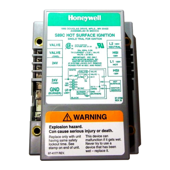
Honeywell
THE S89 AND S890 PROVIDE OPERATING CON
TROL AND SYSTEM SHUTDOWN ON LOSS OF MAIN
BURNER FLAME IN DIRECT IGNITION CENTRAL
HEAT FURNACES AND HEATING APPLIANCES
WITH HOT SURFACE IGNITER.
□ S89C,G,J and S890C,G,J are for systems with a
combination igniter-sensor.
□ S890D.H and S890D.H are for systems with separate
igniter and sensor.
□ S89C,D,J and S890C,D,J lock out after one try for
ignition.
□ S89G,H and S890G.H provide three tries for ignition
before lockout, with 30 sec. min. purge before second
and third tries.
□ S89J and S890J provide 2 or 4 sec. (depending on
model) max. ignition activation periods.
□ S890 provides 30 sec. min. prepurge on initial trial for
ignition.
□ Compatible with Norton 201 and 271 or equivalent hot
surface igniters.
□ S89D.H and S890D.H require a separate sensor
mounted on burner (Q354 recommended).
□ Available with leadwires for line voltage connections.
□ Available with Molex plug for connecting D80D Vent
Damper.
□ Modules can be used on either natural or LP gas; they
provide 100 percent shutoff of gas on lockout.
□ Modules have relay contacts for use with any direct
ignition gas control with max. 2.0 A, 24 Vac rating.
□ Modules use rectification principle for flame sensing.
□ Minus 40° F to +175° F [minus 40° С to +79° C]
temperature rating.
J.A.
Rev. 9-89
oneywell-trade.ru
Form Number 68-0070—1
© Honeywell Inc. 1989
HOT SURFACE
IGNITION
MODULES
Advertisement
Table of Contents

Related Manuals for Honeywell S89C


Summary of Contents for Honeywell S89C
- Page 1 □ S890D.H and S890D.H are for systems with separate igniter and sensor. □ S89C,D,J and S890C,D,J lock out after one try for ignition. □ S89G,H and S890G.H provide three tries for ignition before lockout, with 30 sec. min. purge before second and third tries.
-
Page 2: Specifications
IF YOU HAVE ADDITIONAL QUESTIONS, NEED FURTHER INFORMATION OR WOULD LIKE TO COMMENT ON OUR PRODUCTS OR SERVICES, PLEASE WRITE OR PHONE: 1. YOUR LOCAL HONEYWELL RESIDENTIAL SALES OFFICE (CHECK WHITE PAGES OF YOUR PHONE DIRECTORY). 2. RESIDENTIAL DIVISION CUSTOMER SERVICE HONEYWELL INC., 1885 DOUGLAS DRIVE NORTH... - Page 3 The S89 and S890 provide operating control of a direct ment. ignition system using a hot surface igniter. Additional THERMOSTAT: Compatible with any Honeywell 24 V components required to complete the system must be thermostat and with competitive 24 V thermostats that ordered separately.
-
Page 4: Planning The Installation
Honeywell Residential Division Engi Electronic Ignition Service Manual, form 70-6604. neering review; contact your Honeywell Sales Represen tative for assistance. CORROSIVE CHEMICALS Corrosive chemicals can also attack the module and FREQUENT CYCLING gas control and eventually cause a failure. - Page 5 Any control should be replaced if it does not perform CAUTION properly on checkout or troubleshooting. In addition, re place any module if it is wet or looks like it has ever been 1. Disconnect power supply before beginning wiring wet.
- Page 6 JUMPER TH-W AND 24V TERMINALS. DO NOT REMOVE VENT ALTERNATE LIMIT CONTROLLER LOCATION. DAMPER PLUG. FACTORY TEST TERM INAL. DO NOT USE. LEADWIRE MODEL IS COLOR-CODED AS SHOWN. M2190 FIG. 2—S89C, G, J AND S890C, G, J IN AN ATMOSPHERIC BURNER HEATING SYSTEM.
- Page 7 CONTROLS IN 24V CIRCUIT MUST NOT BE IN LEADWIRE MODEL IS COLOR-CODED AS SHOWN. M2191 GROUND LEG TO TRANSFORMER. FIG. A — S89C, G, J AND S890C.G, J IN AN ATMOSPHERIC BURNER HEATING SYSTEM WITH THE D80D VENT DAMPER. 0070—1...
- Page 8 CONTROLS IN 24V CIRCUIT MUST NOT BE IN GROUND LEG TO TRANSFORMER. CONNECT COLORS OF WIRE AS SHOWN. M2192 FIG. 5—S89C, G, J AND S890C, G, J IN AN ATMOSPHERIC BURNER HEATING SYSTEM WITH D80B VENT DAMPER. DUAL VALVE COMBINATION S89C,G.J/S890C,G,J HOT...
- Page 9 CONTROLS IN 24V CIRCUIT MUST NOT BE IN GROUND LEG TO TRANSFORMER. LEADWIRE MODEL IS COLOR-CODED AS SHOWN. M2194 FIG. 7—S89C,G,J AND S890C,G,J IN A TWO STAGE FAN-ASSISTED COMBUSTION HEATING SYSTEM. .tA.t THERMOSTAT POWER SUPPLY. PROVIDE DISCONNECT MEANS FOR MODULE WITH TH-W TERMINAL AND VENT AND OVERLOAD PROTECTION AS REQUIRED.
- Page 10 DO NOT REMOVE VENT DAMPER PLUG. FACTORY TEST TERM INAL. DO NOT USE. LEADWIRE MODEL IS COLOR-CODED AS SHOWN. M2196 Д LEAVE TP-Z AND Z-W JUMPERS IN PLACE. FIG. 9—S89C,J AND S890C,J IN A HYDRONIC HEATING SYSTEM WITH ATMOSPHERIC BURNER.
- Page 11 CONTROLS IN 24V CIRCUIT MUST NOT BE IN GROUND LEG TO TRANSFORMER. M2197 FIG. 10—S89C,G,J AND S890C,G,J IN A COMMERCIAL WATER HEATING SYSTEM. GAS LEAK TEST: Paint pipe joints with rich soap and CHECKOUT water solution. Bubbles indicate gas leak. Tighten joints Check out the control system: to stop leak.
-
Page 12: Operation
□ Set thermostat below room temperature and wait one minute before continuing. STEP 5: Check Normal Operation. □ Set thermostat or controller above room temperature to call for heat. □ Make sure burner lights smoothly without flashback. □ Make sure burner operates smoothly without floating, CHECK FOR lifting, or flame rollout to the furnace vestibule or heat WAVING... - Page 13 purge, warmup, trial for ignition cycle is repeated a third If the burner lights normally but goes out during the run time. If flame is still not established following the third trial, cycle, the gas control closes and the module initiates a the gas control closes and the module locks out.
-
Page 14: Troubleshooting And Service
TROUBLESHOOTING AND SERVICE ------------------------ IMPORTANT- - ----------------------- shield if necessary to protect the ground wire from 1. The following service procedures are provided as radiant heat. a general guide. Follow appliance manufac — Check temperature at the igniter ceramic or turer’s service instructions if available. - Page 15 START TURN THERMOSTAT NOTE: BEFORE TROUBLESHOOTING, FAMILIARIZE YOURSELF WITH TO CALL FOR HEAT START-UP AND CHECKOUT PROCEDURE. DOES S69/S890 GET CHECK UNE VOLTAGE POWER. POWER (24 VAC NOMINAL)? CHECK LOW VOLTAGE TRANSFORMER. CHECK LIMIT CONTROLLER. CHECK AIR PROVING SWITCH (IF USED). CHECK THERMOSTAT.
- Page 16 EXTERNAL SENSOR. M21gg WIRING FIG. 14—S89/S890 SIMPLIFIED SCHEMATIC. Honeywell Inc. International Sales Offices in all principal cities of the world. Manufacturing in 1885 Douglas Drive N. Australia, Canada, Finland, France, Germany, Japan, Mexico, Netherlands, Golden Valley, MN 55422-4386 Spain, Taiwan, United Kingdom, U.S.A.
Need help?
Do you have a question about the S89C and is the answer not in the manual?
Questions and answers