IFM DTC600 Installation Instructions Manual
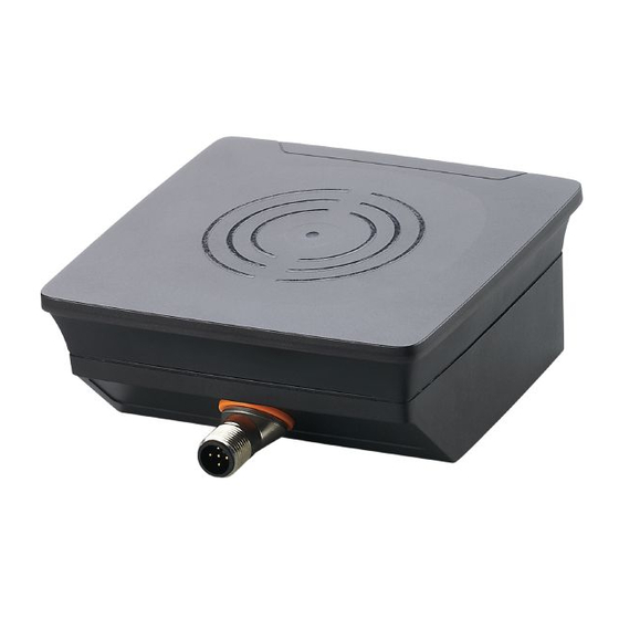
Rf identification system read/write head
Hide thumbs
Also See for DTC600:
- Installation instructions manual (49 pages) ,
- Operating instructions manual (61 pages) ,
- Operating instructions manual (38 pages)
Table of Contents
Advertisement
Quick Links
Advertisement
Table of Contents

Related Manuals for IFM DTC600


Summary of Contents for IFM DTC600
- Page 1 Installation instructions RF identification system Read/write head DTC600...
-
Page 2: Table Of Contents
Contents 1 Preliminary note ���������������������������������������������������������������������������������������������������4 1�1 Symbols used �����������������������������������������������������������������������������������������������4 1�2 Warnings used ����������������������������������������������������������������������������������������������4 2 Safety instructions �����������������������������������������������������������������������������������������������4 2�1 General ���������������������������������������������������������������������������������������������������������4 2�2 Radio equipment ������������������������������������������������������������������������������������������5 2�3 Interference of electronic and medical devices ��������������������������������������������5 3 Functions and features ����������������������������������������������������������������������������������������5 4 Function ���������������������������������������������������������������������������������������������������������������6 4�1 Operating principle ���������������������������������������������������������������������������������������6 4�2 Overview �������������������������������������������������������������������������������������������������������6 5 Installation������������������������������������������������������������������������������������������������������������6... - Page 3 11 Maintenance, repair, disposal ��������������������������������������������������������������������������15 12 Approvals/standards ����������������������������������������������������������������������������������������16 12�1 Radio approvals ����������������������������������������������������������������������������������������16 12�1�1 Overview �������������������������������������������������������������������������������������������16 12�1�2 Europe / EC declaration of conformity ����������������������������������������������16 12�1�3 USA ��������������������������������������������������������������������������������������������������16 12�1�4 Canada ���������������������������������������������������������������������������������������������17 12�1�5 Taiwan ����������������������������������������������������������������������������������������������17 12�1�6 Australia ��������������������������������������������������������������������������������������������18 12�1�7 Singapore �����������������������������������������������������������������������������������������18...
-
Page 4: Preliminary Note
1 Preliminary note Technical data, approvals, accessories and further information → www�ifm�com� 1.1 Symbols used ► Instruction → Cross-reference Important note Non-compliance may result in malfunction or interference� Information Supplementary note 1.2 Warnings used NOTE! Type and source of the hazard >... -
Page 5: 2�2 Radio Equipment
The device may only be used under the operating conditions specified in the data sheet� 3 Functions and features The DTC600 read/write head is used for non-contact reading and writing of RFID tags that conform to the system� The data is transmitted via CAN bus�... -
Page 6: Function
ID tag� A voltage is generated by induction that supplies the data carrier with energy� 4.2 Overview Art� no�: DTC600 Function: Read/write head Type designation: DTCHF HLRWCOUS03 Operating frequency: 13�56 Mhz... -
Page 7: 5�3 Avoiding Interference
For positioning the ID tags the read/write heads are marked with an antenna symbol on the active face� It designates the middle of the integrated antenna coil and has to correspond with the middle of the ID tag� The orientation of the read/write head axis must correspond with the axis of the ID tag coil�... -
Page 8: 5�5�1 Installation With Angle Bracket E80335
5.5.1 Installation with angle bracket E80335 Fig� 3: Installation with angle bracket E80335 5.5.2 Installation with mounting device E80336 The mounting device is used to mount the unit to a clamp� The following clamps can be used: ● E21110 with a rod diameter of 12 mm ●... -
Page 9: 5�5�3 Installation With Fixing Bars E80337
5.5.3 Installation with fixing bars E80337 Fig� 5: Installation with fixing bars E80337 ► Fix the unit with fixing screws to the designated location� 5.6 Mounting distances Fig� 6: Mounting distances Operating mode Distance side (A) Distance front (B) Read and write ≥... -
Page 10: 5�7 Positioning Of The Id Tag
5.7 Positioning of the ID tag ► Align the ID tag on the antenna central axis� > The distance D is indicated in the data sheet Fig� 7: Position the ID tag 6 Electrical connection NOTE! The unit must be connected by a qualified electrician� Device of protection class III (PC III) Electric supply via PELV circuits only�... -
Page 11: 6�1 Wiring
6.2 CAN bus interface The device has a CAN interface� Use cables that are approved for CAN bus� Terminate the cables using terminating resistors (120 Ω). Use ifm's EVC492 cable with integrated terminating resistor as an alternative� 6.3 cULus For devices with cULus approval and the cULus scope of validity: ►... -
Page 12: Indicators
7 Indicators 1: LEDs 2: sensing face Fig� 9: Indicators Status power LED LED signal bar LED CAN LED CAN (green) (4x yellow) status status (red) (green) Ready for operation without ID tag Ready for operation with up to 4 LEDs ID tag are on Read/write successful... -
Page 13: Operation
► Depending on the configuration of the CAN network, adjust the settings of the CAN network under (→ 8.1). More notes on operation can be found in the operating instructions: www�ifm�com 8.1 CANopen The device is delivered with the node ID 32 and a bit rate of 125 Kbits/s�... -
Page 14: Scale Drawing
9 Scale drawing 12,4 M12x1 Fig� 10: Scale drawing The max� tightening torque of the screws when mounting the unit is 0�8 Nm� 10 Technical data The data sheets are available on our website at www�ifm�com�... -
Page 15: 10�1 Detection Range With E80384
10.1 Detection range with E80384 [mm] -200 -150 -100 [mm] Fig� 11: Detection range with E80384 All indications apply to static write operations� If not otherwise stated, they refer to the installation of the unit and of the ID tag in a non-metallic environment�... -
Page 16: Approvals/Standards
The overview of the approval status of a unit is available on our website at www� ifm�com � 12.1.2 Europe / EC declaration of conformity ifm electronic gmbh hereby declares that the DTC600 radio system corresponds to the directive 2014/53/EU� You can find the EC declaration of conformity on our website at: www�ifm�com... -
Page 17: 12�1�4 Canada
12.1.4 Canada IC note: This device complies with Industry Canada license-exempt RSS standards� Operation is subject to the following two conditions: 1� The device may not cause interference, and 2� the user of the device must accept any interference received, including interference that may cause undesired operation�... -
Page 18: 12�1�6 Australia
12.1.6 Australia Use in Australia: 12.1.7 Singapore Complies with IDA Standards DB 103032 The “Equipment Registration” is available on our website at: www�ifm�com...
Need help?
Do you have a question about the DTC600 and is the answer not in the manual?
Questions and answers