Table of Contents
Advertisement
+
6
OPERATION &
MAINTENANCE
MANUAL
WARNING
This equipment uses
Rare Earth Magnets
with a strong magnetic
field. You should not
use, service or work in
the close vicinity
(30cm/1ft) of this
equipment if you are
fitted with a pacemaker
or electromechanical
medical device.
BOSS
X-POT6+ Operation & Maintenance Manual (V1.2 September 2017)
Page 1
TM
Advertisement
Table of Contents

Related Manuals for Boss X-POT 6+


Summary of Contents for Boss X-POT 6+
- Page 1 field. You should not use, service or work in the close vicinity (30cm/1ft) of this equipment if you are fitted with a pacemaker or electromechanical medical device. BOSS X-POT6+ Operation & Maintenance Manual (V1.2 September 2017) Page 1...
-
Page 2: Table Of Contents
35. Bolt Tightening Notes ......................Page 26 36. Electrical Checks & Inspection 37. Decommissioning & Dismantling ....................Page 27 ................Page 28 38. General Assembly Drawing BOSS™ X-POT6+ ................Page 29 39. General Access Drawing BOSS™ X-POT6+ 40. Declaration Of Conformity .......................Page 30 ............................Page 31 41. -
Page 3: Safe Working Distance Statement
BOSS X-POT6+ Operation & Maintenance Manual (V1.2 September 2017) Page 3... -
Page 4: Liability
We reserve the right to make technical changes subject to the future development of the BOSS™ product referred to in this publication. Hence no rights may be derived from technical data, descriptions and illustrations. Technical pictures, drawings and graphs do not necessarily correspond to the actual assemblies or parts as delivered. -
Page 5: Copyright
Consider the implications of errors and incorrect set-up conditions carefully! Disregarding these warnings may lead to: • serious personal injury • overloading of individual components and damage • impair the unit’s function BOSS X-POT6+ Operation & Maintenance Manual (V1.2 September 2017) Page 5... -
Page 6: Purpose & Use Of This Manual
If not in line with conformity statement or if the delivery is incorrect in any other way, the product must not be used. BOSS X-POT6+ Operation & Maintenance Manual (V1.2 September 2017) Page 6... -
Page 7: Transportation, Storage, Unpacking
The in line with directive 2006/42/EC required EMERGENCY-STOP facility is made available by the main power switch on the mounting board – Back Panel, refer to the BOSS™ X-POT6+ Schematic, item 24 on page 10 of this document. PeRsonAL PRoteCtIve eQuIPment... -
Page 8: Exceeding Permitted Pressure &/Or Temperature Levels
12 months. mAIntenAnCe & RePAIR These services may only be carried out when the X-POT6+ is shut down. The BOSS™ X-POT6+ equipment must be taken out of service and guarded against unintentional re- starting until the maintenance work is finished. -
Page 9: Obvious Misuse
• Use in inappropriate system designs and environments. • Use of non-permitted or inappropriate installation materials. PRoduCt desCRIPtIon The BOSS™ X-POT6+ is a sealed system, 2 stage side stream filtration and manual chemical dosing unit. It is a Patented, fully prefabricated, factory tested wall mounted unit incorporating: •... -
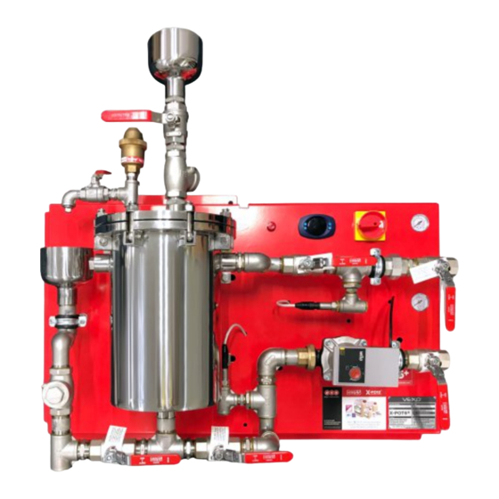
Page 10: Schematics & Component List
ISOLATING VALVE SWING CHECK VALVE PRESSURE TRANSDUCER 1 (DIRTY FLOW) MANUAL VENT TUNDISH ISOLATING VALVE CHEMICAL FILL TUNDISH BOSS™ X-POT6+ VESSEL BODY ISOLATING VALVE SWING CHECK VALVE MAGNET GRATE (INTERNAL) CONTAINING 6 MAGNETS AUTOMATIC AIR VENT BAFFLE PLATE (INTERNAL) MANUAL VENT ISOLATING VALVE... -
Page 11: Operating Principles
The system fluid is drawn from the main system return and into the BOSS™ X-POT6+ vessel. The fluid is drawn through a twin stage filtration system, in the first chamber,... -
Page 12: Markings
MARKINGS THE FOLLOWING MARKINGS AND WARNINGS ARE INSTALLED ON THE X-POT6+ UNIT ® ® INTEGRATED ELECTRONIC SIDE STREAM FILTRATION & DOSING UNIT PUMP SPEED MUST BE SET TO ‘3' BOSS X-POT6+ Operation & Maintenance Manual (V1.2 September 2017) Page 12... -
Page 13: Basic Installation Requirements
1:100. The Power supply to the BOSS™ X-POT6+ is to be provided from the main system pump electrical supply. Therefore, the BOSS™ X-POT6+ will only be activated when the main system pump is running and active. -
Page 14: Electrical
ConneCtIons & WIRInG dIAGRAm BOSS X-POT6+ Operation & Maintenance Manual (V1.2 September 2017) Page 14... -
Page 15: Commissioning
Therefore, the BOSS™ X-POT6+ will only be activated when the main system pumps are running and active. Ensure the power supply to the BOSS™ X-POT6+ is 230V ~ 1 N PE 50Hz via a suitable Fused Spur. The power supply is then connected to the main BOSS™ X-POT6+ Mains Isolation Switch, refer to the unit schematic, item 22 on page 10 (Schematic) of this document. - Page 16 / chilled system should be in the ‘open’ position. Rotate the valve handles to be in-line with the pipework it is connected to. Refer to page 10 for the BOSS™ X-POT6+ Schematic, valve references 1, 3, 8 & 11.
-
Page 17: Control Panel Boss™ X-Pot6
Call Engineer to check connections and replacement of Pump Fail Shutdown the Pump The VEXO ® iX-1 Controller if connected to a BMS, it will send a “Common Fault” signal to draw attention to the user. BOSS X-POT6+ Operation & Maintenance Manual (V1.2 September 2017) Page 17... -
Page 18: Monitoring & Parameters
0 = N/C 1 = N/C Sensor Minimum Pressure 0 Bar 0.0 – 10.0 Bar 10 Bar 0.0 – 10.0 Bar Sensor Maximum Pressure ID Number Pump Hours Alarm Count BOSS X-POT6+ Operation & Maintenance Manual (V1.2 September 2017) Page 18... -
Page 19: Filter Maintenance
1. Disassembly For Filter Replacement The filter replacement may only be carried out when the X-POT6+ is shut down and the BOSS™ X-POT6+ has been hydraulically isolated from the main system water pressure and also electrically isolated from the main system power supply. -
Page 20: To Clean And Replace The Filters
Controller (21). The screen should be blank and off and the pump will not run. Manually close the 1” Isolating Valves (1 & 3) on the Dirty Flow into the BOSS™ X-POT6+ Manually close the 1” Isolating Valves (8 & 11) on the Clean Return from the BOSS™... - Page 21 28. Manually close the 1” Isolating Valve (12). This will close the BOSS™ X-POT6+ Vessel (4) to drain. 29. Slowly manually open the 1” Isolating Valves (1 & 3) on the Dirty Flow into the BOSS™ X-POT6+. This will now let system water into the BOSS™ X-POT6+ Vessel.
-
Page 22: Dosing & Water Treatment Chemicals
To manually dose the system, it may only be carried when the system is shut down and the BOSS™ X-POT6+ has been hydraulically isolated from the main system water pressure and also electrically isolated from the main system power supply. -
Page 23: To Manually Dose The System With Water Treatment Chemicals
Manually close the 1” Isolating Valves (1&3) on the Dirty Flow to the BOSS™ X-POT6+. Manually close the 1” Isolating Valves (8 & 11) on the Clean Return from the BOSS™ X-POT6+. - Page 24 25. Replace the ½” plug and manually close the ½” Manual Vent Isolating Valve (19). This will close the BOSS™ X-POT6+ Vessel (4) to atmosphere. 26. Slowly manually open the 1” Isolating Valves (1 & 3) on the Dirty Flow into the BOSS™ X-POT6+. This will now let system water into the BOSS™ X-POT6+ Vessel.
- Page 25 39. Manually close the 1” Isolating Valve (12). This will close the BOSS™ X-POT6+ Vessel (4) to drain. 40. Slowly manually open the 1” Isolating Valves (1 & 3) on the Dirty Flow into the BOSS™ X-POT6+. This will now let system water into the BOSS™ X-POT6+ Vessel.
-
Page 26: Bolt Tightening Notes
BOLT 3 SEQUENCE D then BOLT 7 When the BOSS™ X-POT6+ top flange plate is replaced, ensuring the seal faces are clean and unobstructed. Ensure the Manual Air Vent spout is positioned directly over the Manual Vent Tundish (14). The tightening sequence must be repeated 3 times to guarantee that all the nuts are to the required torque (40Nm). -
Page 27: Decommissioning & Dismantling
The destination of and further processing of the construction components should be carried out in agreement with the relevant waste management service provider. BOSS X-POT6+ Operation & Maintenance Manual (V1.2 September 2017) Page 27... -
Page 28: General Assembly Drawing Boss™ X-Pot6
® GENERAL ASSEMBLY WEAR APPROPRIATE PPE WHEN WARNING! ® OPERATING THE BOSS X-POT6+ INSTALLATION BY QUALIFIED/EXPERIENCED TECHNICIANS ONLY TUNDISH TUNDISH MAN. VENT DIRTY FLOW FILTER FILTER VESSEL VESSEL CLEAN RETURN PUMP ® FRONT SIDE DRAIN DIRTY FLOW MAN. VENT TUNDISH... -
Page 29: General Access Drawing Boss™ X-Pot6
® GENERAL ACCESS WEAR APPROPRIATE PPE WHEN WARNING! ® OPERATING THE BOSS X-POT6+ INSTALLATION BY QUALIFIED/EXPERIENCED TECHNICIANS ONLY NOTE: ALL MEASUREMENTS ARE FOR GUIDANCE SIDE Unobstructed area for dosing TUNDISH FRONT DIRTY FLOW FILTER VESSEL CLEAN RETURN ® DRAIN Unobstructed... -
Page 30: Declaration Of Conformity
BOSS X-POT6+ Operation & Maintenance Manual (V1.2 September 2017) Page 30... -
Page 31: Service History
® SERVICE HISTORY WEAR APPROPRIATE PPE WHEN WARNING! ® OPERATING THE BOSS X-POT6+ INSTALLATION BY QUALIFIED/EXPERIENCED TECHNICIANS ONLY INSTALLED BY: DATE: SERVICED BY: DATE: NOTES: NOTES: SERVICED BY: DATE: SERVICED BY: DATE: NOTES: NOTES: SERVICED BY: DATE: SERVICED BY: DATE:... - Page 32 BOSS™ X-POT is distributed exclusively by BSS Industrial, BOSS Court, 7 Barton Close, Grove Park, Leicester, LE19 1SJ www.bssindustrial.co.uk Tel: 0116 245 5940 X-PO10 and X-POT are trademarks of VEXO International...
Need help?
Do you have a question about the X-POT 6+ and is the answer not in the manual?
Questions and answers