Table of Contents
Advertisement
Quick Links
Advertisement
Table of Contents

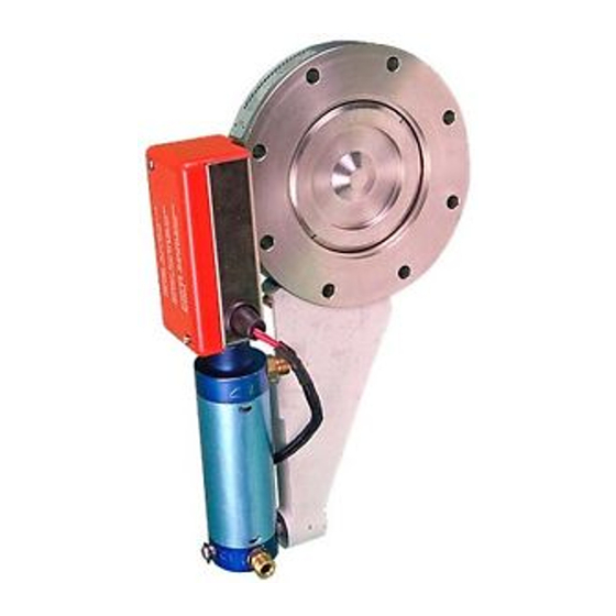
Related Manuals for Edwards QSB63


Summary of Contents for Edwards QSB63
- Page 1 B426-09-880 Issue A Original Instruction Manual QSB63P and QSB100P Pneumatically Operated Valves with Reed Switches Description Item Number QSB63P Pneumatically Operated Valve with Reed Switch B424-09-000 QSB100P Pneumatically Operated Valve with Reed Switch B426-09-000...
- Page 2 The relevant technical documentation has been compiled in accordance with Annex VII Part B. In response to a reasoned request by the national authorities, Edwards Ltd undertakes to provide relevant information on the partly completed machinery (via email).
-
Page 3: Table Of Contents
Service ........................14 Spares ........................14 Index ....................15 For return of equipment, complete the HS Forms at the end of this manual. © Edwards Limited 2009. All rights reserved. Page i Edwards and the Edwards logo are trademarks of Edwards Limited. - Page 4 Technical data ......................4 Position indicator reed switches ..................4 Fixing bolts required to secure the valve ................6 Maintenance plan .......................10 Page ii © Edwards Limited 2009. All rights reserved. Edwards and the Edwards logo are trademarks of Edwards Limited.
-
Page 5: Introduction
All models of the QSB valves are secured in place by the fixing holes in the valve flange. The valve flange faces are sealed by an Edwards Co-Seal or trapped ‘O’ ring. The flange face dimensions are in accordance with ISO1609:1986 (Vacuum Technology - Flange Dimensions). - Page 6 2. Blanking plug ‘O’ ring 6. Screw 3. Valve shaft ‘O’ ring 7. Valve shaft 4. Valve plate ‘O’ ring 8. Blanking plug Page 2 © Edwards Limited 2009. All rights reserved. Edwards and the Edwards logo are trademarks of Edwards Limited.
-
Page 7: Pneumatic Valve Details
13. Reed switch (valve open) 6. Valve shaft 14. Reed switch (valve closed) 7. Screw 15. Pneumatic actuator 8. Link arm 16. Support bracket © Edwards Limited 2009. All rights reserved. Page 3 Edwards and the Edwards logo are trademarks of Edwards Limited. -
Page 8: Technical Data
Max current 500 mA Max power 6 W / 6 VA Cable length Item numbers Valve Item Number QSB63P B424-09-000 QSB100P B426-09-000 Page 4 © Edwards Limited 2009. All rights reserved. Edwards and the Edwards logo are trademarks of Edwards Limited. - Page 9 B426-09-880 Issue A Figure 3 - Dimensions (mm) Valve Size QSB63P 23.5 17.7 235.5 QSB100P 235.5 130.5 © Edwards Limited 2009. All rights reserved. Page 5 Edwards and the Edwards logo are trademarks of Edwards Limited.
-
Page 10: Installation
Table 3 - Fixing bolts required to secure the valve Valve Bolt size Number QSB63P M8 x 65 QSB100P M8 x 70 Page 6 © Edwards Limited 2009. All rights reserved. Edwards and the Edwards logo are trademarks of Edwards Limited. -
Page 11: Pneumatic Connections
5. 5-port control valve 6. Electrical connections 7. QSB valve (electrical fail to closed position) 8. QSB valve (electrical fail to open position) © Edwards Limited 2009. All rights reserved. Page 7 Edwards and the Edwards logo are trademarks of Edwards Limited. -
Page 12: Position Indicator Reed Switch Connections
Figure Figure 5 - Reed switch connections when LED indicator is used Figure 6 - Reed switch connections without LED indicator Page 8 © Edwards Limited 2009. All rights reserved. Edwards and the Edwards logo are trademarks of Edwards Limited. -
Page 13: Operation
Note that if the pneumatic supply fails, the QSB pneumatic valves will probably stay in the same position (open or closed), though this will depend on vibration and other external influences on the valve. © Edwards Limited 2009. All rights reserved. Page 9 Edwards and the Edwards logo are trademarks of Edwards Limited. -
Page 14: Maintenance
As required (typically every 1 x 10 cycles) Replace the valve-shaft ‘O’ ring As required (typically every 1 x 10 cycles) Adjust the position indicator As required Page 10 © Edwards Limited 2009. All rights reserved. Edwards and the Edwards logo are trademarks of Edwards Limited. -
Page 15: Dismantle And Inspect The Valve
4. Lightly grease the new ‘O’ rings with Fomblin grease and fit the ‘O’ rings into the grooves in the valve shaft. 5. Reassemble the valve as described in Section 5.5. © Edwards Limited 2009. All rights reserved. Page 11 Edwards and the Edwards logo are trademarks of Edwards Limited. -
Page 16: Adjust The Position Indicators
A list of possible fault conditions and their possible causes is provided here to assist you in basic fault finding. If you are unable to rectify a fault using this guide, call your supplier or your nearest Edwards Service Centre for help. -
Page 17: Storage And Disposal
Dispose of the QSB valve and any components removed from it safely in accordance with all local and national safety and environmental requirements. Take particular care with any components which have been contaminated with dangerous process substances. © Edwards Limited 2009. All rights reserved. Page 13 Edwards and the Edwards logo are trademarks of Edwards Limited. -
Page 18: Service, Spares And Accessories
The majority of these centres employ Service Engineers who have undergone comprehensive Edwards training courses. Order spare parts and accessories from your nearest Edwards company or distributor. When you order, state for each part required: Model and Item Number of your equipment Serial number Item Number and description of part. -
Page 19: Index
Reed switch connections without LED indicator ..8 Replace the valve plate ‘O’ ring ...... 11 Replace the valve shaft ‘O’ rings ..... 11 Safety ............. 10 © Edwards Limited 2009. All rights reserved. Page 15 Edwards and the Edwards logo are trademarks of Edwards Limited. - Page 20 B426-09-880 Issue C This page has been intentionally left blank. Page 16 © Edwards Limited 2009. All rights reserved. Edwards and the Edwards logo are trademarks of Edwards Limited.
- Page 21 This page has been intentionally left blank.
- Page 22 This page has been intentionally left blank.
- Page 23 Download the latest documents from www.edwardsvacuum.com/HSForms/, follow the procedure in HS1, fill in the electronic HS2 form, print it, sign it, and return the signed copy to Edwards. Note: If we do not receive a completed HS2 form, we will not accept the return of the...
- Page 24 edwardsvacuum.com...
Need help?
Do you have a question about the QSB63 and is the answer not in the manual?
Questions and answers