Advertisement
Quick Links
Control-Display Module Installation Sheet
Description
Control-display modules provide additional operator interface
capability for the life safety system. They can be mounted on
any local rail module, except the 3-CPU3 and 3-ANNCPU3.
Inserts are provided for labeling switches and LEDs.
This document provides installation instructions for the control-
display modules listed below.
Model
Description
3-24R
Twenty-four red LEDs
3-24Y
Twenty-four yellow LEDs
3-24G
Twenty-four green LEDs
3-12RY
Twelve red-over-yellow pairs of LEDs
3-12SG
Twelve LED-switches with green LEDs
3-12SR
Twelve LED-switches with red LEDs
3-12SY
Twelve LED-switches with yellow LEDs
3-12/S1GY
Twelve LED-switches with green-over-yellow LEDs
3-12/S1RY
Twelve LED-switches with red-over-yellow LEDs
3-12/S2Y
Twelve LED-switches with yellow-over-yellow LEDs
3-6/3S1G2Y
Six groups of three LED-switches with green LEDs
(top switch), and yellow LEDs (middle and bottom
switch)
3-6/3S1GYR
Six groups of three LED-switches with green LEDs
(top switch), yellow LEDs (middle switch), and red
LEDs (bottom switch)
3-4/3SGYWR
Four groups of three LED-switches with green LEDs
(top switch), yellow-over-white LEDs (middle
switch), and red LEDs (bottom switch)
Installation
Cautions
•
This product contains components that are sensitive to
electrostatic discharge (ESD). Handle with care.
•
Installing this product with power applied will damage the
equipment. Power down the panel before installing.
© 2013 UTC Fire & Security. All rights reserved.
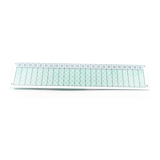
To install a control-display module:
1.
Fill out the label insert. Slip it between the overlay and the
circuit board. See Figure 1.
2.
Insert the left side of the control-display module into the
door frame then push in on the right side until it snaps into
place.
3.
Connect the ribbon cable (P/N 250186) to the rail module
with the red edge of the cable pointed up.
Figure 1: Installation
1 / 2
P/N 270493 • REV 06 • REB 18JAN13
Advertisement

Subscribe to Our Youtube Channel
Related Manuals for Edwards 3-24R


Summary of Contents for Edwards 3-24R
- Page 1 This document provides installation instructions for the control- display modules listed below. Connect the ribbon cable (P/N 250186) to the rail module with the red edge of the cable pointed up. Model Description 3-24R Twenty-four red LEDs Figure 1: Installation 3-24Y Twenty-four yellow LEDs 3-24G...
-
Page 2: Specifications
Specifications Voltage 24 VDC Current Standby 2.0 mA plus 1.5 mA for each active LED Alarm 2.0 mA plus 1.5 mA for each active LED Operating environment Temperature 32 to 120°F (0 to 49°C) Humidity 0 to 93% RH, noncondensing at 90°F (32°C) Contact information For contact information, see www.edwardsutcfs.com.
Need help?
Do you have a question about the 3-24R and is the answer not in the manual?
Questions and answers