Table of Contents
Advertisement
Quick Links
Instruction Manual (C)
SCU-800 Control Unit
STP pump consists of the three-volumed Instruction Manuals.
Instruction Manual (A):
Instruction Manual (B):
Instruction Manual (C):
(This Instruction Manual)
STP pump generic Instruction Manual
STP pump specific information
STP control unit Instruction Manual
Copyright 2016 Edwards Japan Limited. All rights reserved. Printed in Japan.
MT-49E-101-G
Advertisement
Table of Contents
Troubleshooting

Related Manuals for Edwards SCU-800


Summary of Contents for Edwards SCU-800
- Page 1 STP pump consists of the three-volumed Instruction Manuals. Instruction Manual (A): STP pump generic Instruction Manual Instruction Manual (B): STP pump specific information Instruction Manual (C): STP control unit Instruction Manual (This Instruction Manual) Copyright 2016 Edwards Japan Limited. All rights reserved. Printed in Japan.
-
Page 2: Declaration Of Conformity
Note: This declaration covers all product serial numbers from the date this Declaration was signed onwards. Manufacture: June. 2016, Yachiyo Yuji Kato, TMP Technical Senior Manager, Edwards Japan Limited Date and Place June. 2016, Burgess Hill EU representative: Date and Place... - Page 3 The description of this product consists of the three-volumed Instruction Manuals. Read through each Instruction Manual before operation. The separate volume contents of each description are as follows: Instruction Manual (A) STP pump generic Instruction Manual: Introduction Installation of the STP pump ...
- Page 4 This page intentionally blank...
-
Page 5: Table Of Contents
SCU-800 Control Unit for Turbomolecular Pump CONTENTS PAGE Section Title Page INTRODUCTION Scope and definitions Applied standards Limited warranty 1.3.1 Warranty period 1.3.2 Item warranted 1.3.3 Disclaimer 1.3.4 Spare parts Labels Label affixing positions General description 1.6.1 Cable sets TECHNICAL DATA... - Page 6 SCU-800 Control Unit for Turbomolecular Pump CONTENTS (CONTINUED) PAGE Section Title Page 3.11.1 Remote operation setting 3.11.2 Rotational speed setting 3.11.3 TMS setting 3.11.4 Rotational inhibit signal setting 3.11.5 Emergency vent valve setting 3.11.6 Second Damage Limit 3.11.7 Pump air-cooling fan output setting 3.11.8...
- Page 7 SCU-800 Control Unit for Turbomolecular Pump CONTENTS (CONTINUED) PAGE Section Title Page SERIAL COMMUNICATION PROTOCOL Introduction Connection and setting up 5.2.1 Signal connection 5.2.2 Connecting the RS485 5.2.3 Communication parameter setting 5.2.4 Recommended items about communication cable installation 63 Protocol specifications 5.3.1...
- Page 8 SCU-800 Control Unit for Turbomolecular Pump CONTENTS (CONTINUED) PAGE Section Title Page MAINTENANCE Safety functions 7.1.1 Power failure 7.1.2 Operation after a power recovery 7.1.3 Abnormal state of magnetic bearing 7.1.4 Excessive vibration 7.1.5 Motor driver overload 7.1.6 Overheating inside the STP pump 7.1.7...
- Page 9 SCU-800 Control Unit for Turbomolecular Pump CONTENTS (CONTINUED) PAGE Section Title Page SERVICE, SPARES AND ACCESSORIES Introduction Service Spares Accessories MT-49E-101-G Page v...
- Page 10 SCU-800 Control Unit for Turbomolecular Pump ILLUSTRATIONS PAGE Figure Title Page High voltage device caution label Voltage caution label Safety instruction label Connector caution label Voltage rating label Label affixing positions SCU-800 control unit Configuration of the STP pump with the TMS...
- Page 11 SCU-800 Control Unit for Turbomolecular Pump TABLES PAGE Table Title Page Turbomolecular pumps SCU-800 front panel functions SCU-800 front panel functions (continued) SCU-800 rear panel connection STP connection cable specification Power cable User setting data list Causes of "CAUTION" at the self test state...
- Page 12 SCU-800 Control Unit for Turbomolecular Pump PAGE viii This page intentionally blank. MT-49E-101-G Page viii...
-
Page 13: Introduction
This manual provides installation, operation and maintenance instructions for the Edwards SCU-800 control unit (abbreviated to "SCU-800" throughout this manual) for the Turbomolecular pump (STP). You must use the SCU-800 as specified in this manual otherwise the protection provided by the equipment may be impaired. -
Page 14: Applied Standards
This WARRANTY applies to the customer to whom Edwards has delivered this product. 1.3.1 Warranty period Edwards warrants this product against defects for a period of two (2) years from the date of delivery or during the period specified in the agreement made by and between the customer and Edwards. MT-49E-101-G... -
Page 15: Item Warranted
1. This warranty applies only to the product delivered from Edwards to the customer. 2. If any defect is found during this period, Edwards will, at its option, repair or recondition the product free of charge. The costs for repair or replacement of the product after the warranty period has passed will be at your own charge. -
Page 16: Labels
SCU-800 Control Unit for Turbomolecular Pump Labels The following labels are affixed or printed to the SCU-800. Read the contents of the labels before operation. 1. High voltage device caution label The SCU-800 is equipped with a high voltage device. This label warns operators to pay attention to the high voltage device at the maintenance and inspection. -
Page 17: Voltage Rating Label
Figure 4 - Connector caution label 5. Voltage rating label This label describes the rated voltage of the SCU-800. Use voltage specified in this label. Some pumps can be operated in the input voltage between 100 - 120V inclusive. Confirm the specific pumps in Section 2, "TECHNICAL DATA". -
Page 18: Label Affixing Positions
SCU-800 Control Unit for Turbomolecular Pump Label affixing positions Refer to Section 1.4 for the details of the labels 1 to 5. Figure 6 - Label affixing positions High voltage device caution label Voltage caution label Safety instruction label Connector caution label... -
Page 19: General Description
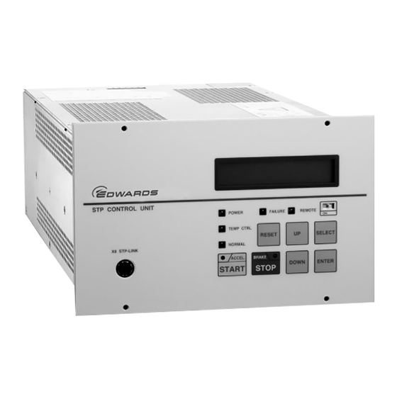
SCU-800 Control Unit for Turbomolecular Pump General description The SCU-800 is the control unit required to drive the STP series of turbomolecular pumps. The SCU-800 converts the single-phase line supply voltage into a 3-phase d.c. voltage to drive the pump motor. -
Page 20: Cable Sets
Figure 8 shows a typical TMS system installation. System connections and cables differ according to the type of pump connected to the SCU-800. Refer to the STP pump Instruction Manual (A) and (B) for full details of connection cables and system connections. -
Page 21: Technical Data
SCU-800 Control Unit for Turbomolecular Pump TECHNICAL DATA SCU-800 specifications Applicable pump STP-603/1003 series STP-H301/H451 series STP-H803/H1303 series STP-A803/A1303 series STP-A1603 series Input voltage: For STP-603/1003 series 100 to 120 Va.c., 200 to 240 Va.c. For STP-H301/H451 series 100 to 120 Va.c., 200 to 240 Va.c. - Page 22 SCU-800 Control Unit for Turbomolecular Pump (Push-button switch•Green) Operation switch START (Push-button switch•Dark Grey) STOP (Push-button switch•Grey) RESET SELECT (Push-button switch•Grey) (Push-button switch•Grey) (Push-button switch•Grey) DOWN (Push-button switch•Grey) ENTER (Slide switch•White) MANUAL/REMOTE changeover Panel indication LED ACCEL. (Green LED) NORMAL...
- Page 23 SCU-800 Control Unit for Turbomolecular Pump X 1 P C O N N E C T OR 110.5 132.5 122.5 Figure 9 - SCU-800 dimensions (mm) * Screw stopper Note: The size of the attached screws for the rubber feet is M3×12.
- Page 24 SCU-800 Control Unit for Turbomolecular Pump This page intentionally blank. MT-49E-101-G Page 12...
-
Page 25: Installation
Unpacking Check outer package for damage and that the delivery note corresponds to the purchase order. If the STP control unit is damaged, contact Edwards or their distributor. Note: It is recommended to keep the packaging materials, such as the corrugated fibreboard container and cushioning material for possible re-use. - Page 26 LCD panel messages, and other. FAILURE LED (Red LED) Illuminates when an abnormality/error occurs on the STP pump or SCU-800. LCD panel simultaneously displays an error message. RESET switch (Flat panel switch, grey. Valid in MANUAL only.) Alarm reset function. Tuning function.
- Page 27 TEMP CTRL LED (Green LED) illuminates when the TMS unit is (optional accessory) operational. POWER LED (Green LED) Illuminates when power is on. Extinguishes when backup power is being supplied. Table 3 - SCU-800 front panel functions (continued) MT-49E-101-G Page 15...
-
Page 28: Rear Panel
. DO NOT touch the terminal. Doing so may result in electric shock. When connecting/disconnecting the connecter, always power off the SCU-800 (turn the MAIN POWER "OFF") and isolate (Lockout/Tagout) the electrical energy source, water and gas, and other energy sources on the vacuum equipment. -
Page 29: Precautions Before Installation
Insulation test CAUTION The varistor for the power supply line protection is installed in the SCU-800. DO NOT perform the insulation test with the varistor installed. Doing so may result in product damage. DO NOT perform an insulation test on the SCU-800. When performing the insulation test on your equipment, ensure that you disconnect the SCU-800 from the equipment that is to be insulation tested, so that the test voltage is not applied to the SCU-800. -
Page 30: Installation Area
The minimum bending radius of the STP connection cable is 200 mm (8"). DO NOT bend the cables excessively and beware of any obstacles when installing the SCU-800. In addition, leave enough space to install other cables without bending them excessively. -
Page 31: Attaching The Scu-800 To A Rack
Attaching the SCU-800 to a rack CAUTION The SCU-800 cannot be supported with only the 4 screws on the front panel. Always support it from the bottom using a support angle. When installing the SCU-800, DO NOT block the ventilation port of the SCU-800 by the support angle or other things. -
Page 32: Cable Connection
CAUTION Use the STP connection cable and the power cable that Edwards has specified. The use of other cables may result in product damage. Align the position of the guide key of the connectors and insert vertically so as not to bend the pins. If a pin is bent, not only may the connector not function normally, but it may make the pins contact, resulting in a malfunction. -
Page 33: Stp Connection Cable
SCU-800 Control Unit for Turbomolecular Pump 3.6.1 STP connection cable Connect the receptacle (socket) side of the STP connection cable to the STP connector on the STP pump and connect the plug (pin) side to "P.CONNECTOR X1" on the SCU-800. NOTE)3 52.5 52.5... -
Page 34: Tms Connection Cable
Connect the plug (pin) side of the TMS connection cable to the "TMS X5" of the TMS control unit. The SCU-800 TMS unit is used with specified STP pumps. Refer to the STP pump Instruction Manual (B) for the cable connection method. -
Page 35: Power Cable
Ensure that the supply voltage is as indicated on the SCU-800 information label. Connect the power cable to the "AC POWER X2" connector on the SCU-800. Connect the power cable for the SCU-800 side to the "AC POWER X2" on the SCU-800 rear panel as shown in Table 6. - Page 36 SCU-800 Control Unit for Turbomolecular Pump CON1 pin Cable Colour Remarks Black 1 Single-phase 200 to 240 Va.c. (200 V specification), 50/60 Hz, 6 A maximum, or Single-phase 100 to 120 Va.c. (100 V specification), Black 2 50/60 Hz, 12 A maximum...
-
Page 37: Connecting To Semiconductor Equipment
3.7.1 Connecting to power The SCU-800 receives its power from the semiconductor equipment electrical distribution system via a circuit breaker. Electrical energy isolation (Lockout/Tagout) is achieved by opening the main disconnect device or circuit breaker of the semiconductor equipment, thereby removing power from the STP pump. -
Page 38: Remote Communication
3.8.1 Parallel communication The SCU-800 is fitted with a remote communication port, "REMOTE X7" (refer to Figure 19) to allow remote input and output signal control via input and output remote signals. This connector is a D-Sub type (37-pins, socket) that conforms to MIL-C-24308. The screw for connector is M2.6. -
Page 39: Adjustment Methods
When changing the length of the STP connection cable (not when changing the length of the power cable). Connecting the same model but a different serial number of the STP pump to the SCU-800 after the tuning is performed. The error message "CAUTION : Coupling is Changed" is displayed upon performing the self test. - Page 40 Once tuning is completed, re-tuning is not required unless the configuration (the STP pump serial number, the SCU-800 serial number, and the STP connection cable length) is changed. Although the STP pump produces an abnormal noise during tuning, this is not an indication of abnormality.
-
Page 41: Change Of Data After Tuning
SCU-800 Control Unit for Turbomolecular Pump 3.9.3 Change of data after tuning The user setting may be changed because of the change of the configuration of the STP pump and STP control unit after "CAUTION" message is displayed. Confirm the setting shown in Table 7 after tuning, and reconfigure the setting when the user setting has changed. -
Page 42: Confirmation Mode
SCU-800 Control Unit for Turbomolecular Pump 3.10 Confirmation mode Confirmation mode is used to check the status of the STP pump and SCU-800. The following items can be checked in Confirmation mode: 1. Version information. 2. Individual information (serial number, total hours of running, number of starts and damage of the bearing). - Page 43 SCU-800 Control Unit for Turbomolecular Pump MT-49E-101-G Page 31...
-
Page 44: Parameter Set Mode
Enable/Disable the emergency vent valve function. When a failure of the magnetic bearing is detected, in the state of effective, 24 DCV is output between the TMS connector X5-19 pin and 20 pin. Disable the function when the emergency vent valve is not fitted on the STP pump connected to the SCU-800. MT-49E-101-G... -
Page 45: Second Damage Limit
SCU-800 Control Unit for Turbomolecular Pump 3.11.6 Second Damage Limit setting Enable/Disable the rotational operation after "Second Damage Limit" occurs. When setting to "ENABLE", "START NOT ALLOWED" is displayed and the rotational operation cannot be performed. When setting to "DISABLE", "Second Damage Limit" is displayed, though the rotational operation can be performed. -
Page 46: Warning Function Setting
SCU-800 Control Unit for Turbomolecular Pump 3.11.8 Warning function setting Refer to Section 7.2, "WARNING Message Function" for the detail of the "WARNING" function. 1. Warning Damage Point Enable/Disable Damage limit of the bearing warning function. When setting to "ENABLE" and the Damage limit of the bearing exceeds the setting value, a warning message is displayed. -
Page 47: Serial Port Com1 Setting
SCU-800 Control Unit for Turbomolecular Pump 3.11.9 Serial port COM1 setting 1. Baud rate Set the communication speed. Maximum 56,000 bps can be set. 2. Bit length Set the bit number of the communication data to 7 or 8. 3. Stop bit Set the stop bits number to 1 or 2. -
Page 48: Parameter Setting Procedure
SCU-800 Control Unit for Turbomolecular Pump 3.11.14 Parameter setting procedure Refer to Figure 23 to Figure 26. 1. Press the "UP" and "SELECT" switches simultaneously to enter the Parameter Set Mode. The setting options detailed from Section 3.11.1 to 3.11.12 is each displayed in order. -
Page 49: Parameter Setting Method
SCU-800 Control Unit for Turbomolecular Pump DOWN Levitation NORM:******rpm …… ENTER SELECT SELECT Remote Mode Remote Mode Remote Mode I/O Remote COM1 COM2 Remote Mode Remote Mode COM3:RS485/Lon/D-Net STP-Link Speed Set Point Speed Set Point xxxx rpm xxxx rpm TMS Function... -
Page 50: Parameter Setting Method (Continued)
SCU-800 Control Unit for Turbomolecular Pump Warning Function Warning Damage point Warning Damage point DISABLE ENABLE ENTER to modify ENTER SELECT Warning Imbalance Warning Imbalance DISABLE ENABLE Warning Pump Runtime Warning Pump Runtime DISABLE ENABLE PumpRuntime Setpoint PumpRuntime Setpoint XXXXXXX H... - Page 51 SCU-800 Control Unit for Turbomolecular Pump Serial Port COM1 Set COM1:Baud Rate COM1:Baud Rate …… ***** ***** ENTER to modify ENTER SELECT COM1:Bit Length COM1:Bit Length COM1:Stop bit COM1:Stop bit COM1:Parity COM1:Parity None Even COM1:Parity COM1:Driver Type COM1:Driver Type RS232...
- Page 52 SCU-800 Control Unit for Turbomolecular Pump Available "Baud Rate" are 110, 300, 600, 1200, 2400, 4800, 9600, 14400, 19200, 28800, 38400, and 56000 bps. Available "RS485ID" is between 1and 127. The Serial Port COM2 setting menu composition is the same as the Serial Port COM1 setting. Only "RS485 (Single)" and "RS485 (Multi)"...
-
Page 53: Parameter Setting Method (Continued)
SCU-800 Control Unit for Turbomolecular Pump DOWN SELECT STORAGE STORAGE ENTER ENTER STORAGE IN PROGRESS STORAGE STORAGE NOT OK / TIME OUT SELECT SELECT 2002/APR/01 12:00 2002/APR/01 12:00 ENTER to adjust Year: 2002 ENTER SELECT 2002/APR/01 12:00 Month: 04 (APR) -
Page 54: Manual Operation Mode
SCU-800 Control Unit for Turbomolecular Pump 3.12 Manual operation mode The operation of the TMS heater, TMS water valve, pump air-cooling fan, and the emergency vent valve can be inspected in manual operation mode. However, the manual operation cannot be performed in the remote operation or using different TMS voltage. -
Page 55: Operation
STP pump is rotating 4.1.1 Confirmation before starting After completing the installation of the STP pump and the SCU-800, carry out the following checks before starting: 1. Ensure the STP pump and the SCU-800 are installed correctly (refer to Section 3). -
Page 56: Powering On
Self test Refer to Figure 28. 1. Switch the MAIN POWER to "ON", located on the SCU-800 rear panel, refer to Figure 10. (To prevent incorrect operation, a metal fitting is attached to the breaker. Loosen the screw, lift the metal fitting and secure it.) The SCU-800 performs a self test and "Autotest"... -
Page 57: How To Start/Stop The Stp Pump
Manual start/stop the STP pump To manually start/stop the STP pump, slide the "MANUAL/REMOTE" changeover switch on the SCU-800 front panel from the "ON" position, refer to Figure 9. The "REMOTE" LED will extinguish. 4.4.1 Starting the STP pump 1. - Page 58 SCU-800 Control Unit for Turbomolecular Pump Software Version 49_A *.* Autotest 2002/MAY/20 15:40 Autotest STP-603/1003 Autotest complete Levitation TMS TEMP : **°C ACCEL : ***00rpm TMS TEMP :** °C NORM : ***00rpm TMS TEMP :** °C BRAKE : ***00rpm TMS TEMP :** °C Figure 28 - Operational procedures A.
-
Page 59: Remote Operation
SCU-800 Control Unit for Turbomolecular Pump Remote operation To select remote operation, slide the "MANUAL/REMOTE" changeover switch on the SCU-800 front panel to "ON", refer to Figure 9. The "REMOTE" LED illuminates. 4.5.1 Input signal pins Use input signal pins according to Table 9 and Figure 29. Remote input signals are set to the parallel port in the remote setting and function during REMOTE operation only, except pins for inputting the ROTATION INHIBIT. -
Page 60: Remote X7 Input Signal Pins
SCU-800 Control Unit for Turbomolecular Pump Description Pins for inputting the START signal. The following two methods are available: 1) Short the circuits between (1)-(21). Then, short the circuits between (3)-(21) for 0.3 seconds or more. However, when inputting this START signal simultaneously with switching "ON"... -
Page 61: Output Signal Pins
SCU-800 Control Unit for Turbomolecular Pump +12V COM (0V) 2.2kΩ +12V START IN 2.2kΩ +12V STOP IN (21 ) 2.2kΩ +12V RESET IN (22) 2.2kΩ +12V INHIBIT IN 2.2kΩ +12V REM_IN_OPT1 2.2kΩ +12V REM_IN_OPT2 (23) (19) (20) (31) (34) In case of Start 1) D. -
Page 62: Remote X7 Output Signal Pins
SCU-800 Control Unit for Turbomolecular Pump Description Pins for outputting the STP pump REMOTE SELECTION state signal. When the MANUAL/REMOTE changeover switch on the front panel is set to ON (remote side), these pins are closed ("REMOTE" operation). Pins for outputting the POWER ON state signal. -
Page 63: Remote X7 Output Signal Pins
SCU-800 Control Unit for Turbomolecular Pump REMOTE N.O OUT (27) POWER N.O OUT (28) ACCELERTION (10) N.O OUT (29) N.O OUT (11) NORMAL (30) (12) N.C OUT BRAKE (13) (32) N.O OUT N.O OUT (14) (33) ALARM N.C OUT (15) N.O OUT... -
Page 64: Remote Setting
SCU-800 Control Unit for Turbomolecular Pump Table 11 shows the rated contacts for relays CR1 to CR10 in Figure 30. Resistance Load (COS Ø=1) Rated Load 125 VAC, 0.5 A 24 VDC, 1 A Rated Current Maximum Contact Point Current Maximum Open/Close Capacity AC: 62.5 VA... -
Page 65: Rotation Inhibit Signal
SCU-800 Control Unit for Turbomolecular Pump Rotation INHIBIT signal When using rotation INHIBIT signal, set the rotation INHIBIT function to the "ENALBE" according to Section 3.11, "Parameter set mode". Relations between rotation INHIBIT signal input and pump operation state are shown in Table 13. -
Page 66: Starting The Stp Pump After Stopping
Table 14 - Reset operation during remote operation (REMOTE X7) Powering OFF Turn the MAIN POWER "OFF" on the SCU-800 rear panel when all three LEDs "ACCEL.", "NORMAL" and "BRAKE" extinguish. The magnetic bearing stops, the rotor stops, and the "POWER" LED extinguishes. -
Page 67: Operating The Tms Unit (For Use With The Tms Unit)
While the TMS unit is in operation, the "TEMP CTRL" LED illuminates on the SCU-800. When STP pump is in the power ON state, the TMS unit operates regardless of the status of the SCU-800. When the STP pump is the cause of the malfunction, the TMS unit is stopped. 4.8.3 Setting the TMS unit function When the "TEMP CTRL"... - Page 68 SCU-800 Control Unit for Turbomolecular Pump This page intentionally blank. MT-49E-101-G Page 56...
-
Page 69: Serial Communication Protocol
The SCU-800 is provided with compliant serial interface. Prepare the user application software according to this instruction manual. Operation instructions and information, such as the running state and setting values of the STP pump (information which appears on the LCD of the SCU-800) can be obtained with the software. -
Page 70: Connection And Setting Up
SCU-800 Control Unit for Turbomolecular Pump Connection and setting up 5.2.1 Signal connection The STP control unit is equipped with 3 serial ports COM1, COM2 and STP-Link as a standard. Details of the serial ports COM1 and COM2 are as follows: Serial Port COM1 (shared use by the RS232/485) Connect the PC serial port to connectors X3A or X3B (a D-Sub9-pin, socket) on the rear panel. -
Page 71: X6 Pin Position
SCU-800 Control Unit for Turbomolecular Pump Serial Port COM2 (exclusively used in the RS485) Connect D+/D- to connector X6 on the rear panel (D-Sub 9 pin, socket) according to Table 16. Other pins are reserved for Input/Output remote function, accordingly, there is no connection to these pins. -
Page 72: Connecting The Rs485
1.2 km or less. Connect the terminator to the communication devises at both ends of the transmission line. The terminator (120 Ω, 0.25 W) is required for connection. (SCU-800 does not have terminator setting function) 7 (D–) (connector X3 120Ω... - Page 73 SCU-800 Control Unit for Turbomolecular Pump Because the device driving a communication bus does not exist in the state of no communication, a noise may lead unstable signal which causes communication failure such as a flaming error. When the communication failure is occurred, connect one external pull up and pull down resistance to the PC side to provide a FAIL-SAFE bias.
-
Page 74: Communication Parameter Setting
Section 3.11, "Parameter set mode". To use the operational commands of the SCU-800 (START, STOP, RESET), set the MANUAL/REMOTE changeover switch on the SCU-800 to "ON", and set a port to use the Remote mode, refer to Figure 9. -
Page 75: Recommended Items About Communication Cable Installation
SCU-800 Control Unit for Turbomolecular Pump 5.2.4 Recommended items about communication cable installation Noise generated by many factors such as the type or length of cable, communication speed, and different communication devices may cause the communication failure with a serial port. It is very difficult to prevent a communication failure completely. - Page 76 SCU-800 Control Unit for Turbomolecular Pump DO NOT bundle a communication line with a protective earth conductor or a power line. Moreover, keep away a communication line from the apparatus used as a noise source as much as possible.
- Page 77 SCU-800 Control Unit for Turbomolecular Pump DO NOT insert or remove a communication cable while a communication device and a STP pump are turned ON the power. Communication interface circuit may break down if surge voltage caused by such as potential difference of communication interfaces or static electricity is applied to communication line.
-
Page 78: Protocol Specifications
SCU-800 Control Unit for Turbomolecular Pump Protocol specifications 5.3.1 General description The STP serial communication protocol enables the SIM to receive the communication command (Figure 41, item 1), transmitted from the PC and send a response (Figure 41, item 2), following the communication command. -
Page 79: Standard Transmission Frame (In The Rs232/Rs485 Single Point Connection)
SCU-800 Control Unit for Turbomolecular Pump 5.3.2 Standard transmission frame (in the RS232/RS485 single point connection) The transmission frame used in the RS232/RS485 single point connection has a single block or multiple transmission blocks. The transmission block consists of a start control character, data block No. -
Page 80: Control Command
SCU-800 Control Unit for Turbomolecular Pump 5.3.3 Control command (in the RS232/RS485 single point connection) A control command is used when transmitting a pump operation command and a setting change command to the SIM. The first character of the control command in the RS232/RS485 single point connection is "Sp"... - Page 81 SCU-800 Control Unit for Turbomolecular Pump Next, the preceding SIM->PC character is "Ack", the PC continues instructing the control command (the 2nd block). PC->SIM Stx Etx LRC SIM->PC Ack or Nak Always assign less than 510 characters (n< 510) to the parameter so that the message is less than 512 characters.
-
Page 82: Transmission Data Format
SCU-800 Control Unit for Turbomolecular Pump Always assign less than 254 characters (n< 254) to the parameter so that the message is less than 256 characters. Next, the preceding SIM->PC character is "Ack", the instructed query command is executed and the SIM returns the following response (1st block). -
Page 83: Error Control
SCU-800 Control Unit for Turbomolecular Pump ASCII However, when the MSB (most significant bit) is always 0 when data length is 7 bits, LRC is set to 5.3.7 Error control Transmit the transmission frame repeatedly from the PC when the SIM transmits "Nak" (parity check error). -
Page 84: Transmission Frame In The Rs485 Multi-Point Connection
SCU-800 Control Unit for Turbomolecular Pump 5.3.8 Transmission frame in the RS485 multi-point connection To identify a network frame and ensure the compatibility with a standard transmission frame, add a network frame ID character "@" and a title of 3 characters of network frame number to the transmission frame in the RS485 multi-point connection. -
Page 85: Control Command In The Rs485 Multi-Point Connection
SCU-800 Control Unit for Turbomolecular Pump "@" is used as a network frame ID character. "Stx" is a start character of each transmission block, and "Etb" is an end character of the transmission block of a message of 255 characters. - Page 86 SCU-800 Control Unit for Turbomolecular Pump Transmission frame when data is transmitted to two blocks (message is more than 256 characters and less than 512 characters): Designate the control command (the 1st block) on the PC. PC->SIM @ F Stx 0...
-
Page 87: Query Command In The Rs485 Multi-Point Connection
SCU-800 Control Unit for Turbomolecular Pump 5.3.10 Query command in the RS485 multi-point connection The query command to be used when a pump operation instruction or a setting change instruction is transmitted from the SIM and is arranged in the order specified below. The top is "?" (HEX code "3F") and ASCII characters corresponding to the respective function code and parameter follow. -
Page 88: Broadcasting Command In The Rs485 Multi-Point Connection
SCU-800 Control Unit for Turbomolecular Pump 5.3.11 Broadcasting command in the RS485 multi-point connection The START or STOP of STP pump operation command can be concurrently instructed to all the multi-connected SIMs. Always assign 0 (HEX code "30", "30") to network frame number. Note that there is no response from the respective SIM. -
Page 89: Application Note
SCU-800 Control Unit for Turbomolecular Pump 5.3.12 Application note Noise generated by many factors such as the type or length of cable, communication speed, and different communication devices may cause the communication failure with a serial port. It is very difficult to prevent a communication failure completely. -
Page 90: Example Of Answer Resending Process
SCU-800 Control Unit for Turbomolecular Pump Always check the LRC checksum of answer data. When LRC checksum is incorrect, do not use the data. When the incorrect data caused by noise is accepted, parameters might be set unexpected values. In this case, the processing of the tool application may determine to be a communication failure. - Page 91 SCU-800 Control Unit for Turbomolecular Pump This procedure is not necessary Communication cycle start if TMP connection number = 1. RS485 multipoint connection? Address selection: First TMP Command sending process Succeeded? Answer receiving process Succeeded? Decode process Error process RS485 multipoint...
-
Page 92: Example Of Command Sending Process
SCU-800 Control Unit for Turbomolecular Pump This procedure is not necessary if total block N = 1. Send command (N blocks) *1 When using RS485 to communicate, switch the PC side from sending state to receiving state within 5 sec. -
Page 93: Command Specifications
Reads the errors being detected. ReadModFonct Reads the pump operation mode and the errors being detected. ReadVersion Reads the software version of the SCU-800. ReadCounters Reads serial number, running time and start counter. ReadSetPoint Reads the setting values of the speed set point and the TMS temperature. -
Page 94: Readmeas
Function: Sends the pump operation commands START, STOP and RESET. These commands function in the same way as when each switch of the SCU-800 is pressed. They are valid when MANUAL/REMOTE changeover switch on the SCU-800 is "ON". Refer to Section 3.11, "Parameter set mode". -
Page 95: Readfailmess
SCU-800 Control Unit for Turbomolecular Pump Parameter Item Data format Remark Pump operation command 8-bits hexadecimal coded Refer to Table 21 ASCII Pump operation command Value START STOP RESET Table 21 - Pump operation commands Example: Pump operation command : RESET operation = 4 = 04... - Page 96 8-bits hexadecimal coded ASCII The maximum number of errors may differ depending upon the software version of SCU-800. It is recommended that an application be designed as variable-length data. Value corresponding to the error message is transmitted, (refer to Table 22 and Table 23). The most recent error has the largest parameter number.
-
Page 97: Error Message Values
SCU-800 Control Unit for Turbomolecular Pump Error message Value Error message Value Ram error DSP->PCB Com Fail Eeprom Error PCB->DSP Com Fail TMS Higher Temp TMS Sensor Lost TMS Breaker Trip Tuning Error 1 TMS Overheat Tuning Error 2 Mains Failure... -
Page 98: Readmodfonct
8-bits hexadecimal coded ASCII The maximum number of errors may differ depending upon the software version of SCU-800. It is recommended that an application be designed as variable-length data. Value corresponding to the error message is transmitted (refer to Table 22 and Table 23). The most recent error has the largest parameter number. -
Page 99: Pump Operation Mode
SCU-800 Control Unit for Turbomolecular Pump Pump operation mode Value Levitation No Levitation Acceleration Normal Deceleration (Brake) Autotest Tuning Tuning Complete (Updating control loop S/W) (Waiting to Update Driver S/W) (Updating Driver S/W) Table 24 - Pump operation mode Example:... -
Page 100: Readversion
SCU-800 Control Unit for Turbomolecular Pump 5.4.6 ReadVersion Function: Read the software version of the SCU-800. Transmission frame: PC->SIM Stx Etx LRC SIM->PC PC->SIM SIM->PC Stx Parameter 1 to 24 Etx LRC Parameter Item Data format Remarks 1 to 16... -
Page 101: Readcounters
SCU-800 Control Unit for Turbomolecular Pump 5.4.7 ReadCounters Function: Reads serial number, running time and start counter. Transmission frame: PC->SIM Stx Etx LRC SIM->PC PC->SIM SIM->PC Stx Parameter 1 to 23 Etx LRC Parameter Item Data format Remarks 1 to 10... -
Page 102: Readsetpoint
SCU-800 Control Unit for Turbomolecular Pump 5.4.8 ReadSetPoint Function: Reads the setting value of the "Speed Set Point" and TMS temperature. The "Speed Set Point" data is the same data as that of "ReadSpeedSetPoint". Transmission frame: PC->SIM Stx Etx LRC SIM->PC... -
Page 103: Readstatus
SCU-800 Control Unit for Turbomolecular Pump Parameter Item Data format Remark Motor temperature 16-bits hexadecimal coded (Unit: ºC) ASCII Example: Motor temperature : 0014 = 20 ºC (68 ºF) Parameter ASCII 30 30 31 34 5.4.10 ReadStatus Function: Reads various settings (Remote mode, TMS function, INHIBIT, Emergency vent valve). -
Page 104: Readevents
SCU-800 Control Unit for Turbomolecular Pump Remote mode Value I/O Remote COM1 COM2 STP-Link [System reservation] 3, 4, 7 Table 25 - Remote mode Example: Remote mode setting : 01 = I/O Remote TMS function setting : 00 = ENABLE... -
Page 105: Setspeedsetpoint
SCU-800 Control Unit for Turbomolecular Pump Parameter Item Data format Remarks The number of 8-bits hexadecimal coded Up to 10 errors "Error Record" ASCII 2 to 11 Error Record 1 to 8-bits hexadecimal coded Error Record 10 ASCII Value corresponding to the error message is transmitted (refer to Table 22 and Table 23). The most recent error has the smallest parameter number. -
Page 106: Readspeedsetpoint
When the parameter value is smaller than half of rated rotational speed, it is automatically set to half of rated rotational speed. The value of "Speed Set Point" displayed in LCD of SCU-800 is in increments of 500 rpm. Example:... -
Page 107: Readmodfonctwithwarning
8-bits hexadecimal coded ASCII The maximum number of errors may differ depending upon the software version of the SCU-800. It is recommended that an application be designed as variable-length data. Value corresponding to the error message is transmitted. (see Table 22 and Table 23) The recent error has the largest parameter number. - Page 108 SCU-800 Control Unit for Turbomolecular Pump Warning message 16-bits hex value Remarks 0001 [System reservation] WARNING: Bad Pump Transmit WARNING: Second Damage Limit 0002 see 7.3.3 WARNING: First Damage Limit 0004 see 7.3.2 WARNING: Imbalance X_H 0008 see 7.3.4 WARNING: Imbalance X_B 0010 see 7.3.4...
- Page 109 SCU-800 Control Unit for Turbomolecular Pump Example: Pump operation mode : 01 = 1 = Levitation WARNING being detected : 0098 = 0008 OR 0010 OR 0080 3 warnings of "WARNING: Imbalance X_H", "WARNING: Imbalance X_B" and "WARNING: Pump Overload"...
-
Page 110: Readmeasvalue
SCU-800 Control Unit for Turbomolecular Pump 5.4.15 ReadMeasValue Function: Reads the TMS temperature, motor temperature and measured rotational speed. The motor temperature value is the same temperature as "ReadMotorTemp". The measured rotational speed value is the same as "ReadMeas" parameter 2 (Measured rotational speed). - Page 111 SCU-800 Control Unit for Turbomolecular Pump Example: TMS temperature: 003C = 60 ºC (140ºF) Motor temperature: 0014 = 20 ºC (68ºF) Measured rotational speed: 02DC = 732 Hz = 43,920 rpm Parameter ASCII Parameter ASCII 30 30 33 43 Parameter...
- Page 112 SCU-800 Control Unit for Turbomolecular Pump This page intentionally blank. MT-49E-101-G Page 100...
-
Page 113: Stp-Link
SCU-800 Control Unit for Turbomolecular Pump STP-Link The "STP-Link" is a Windows application for operating the STP pump, confirming the pump status or setting various settings. Table 27 shows the principal functions. See the Instruction Manual of the "STP-Link" for the detailed specification and operating method. - Page 114 SCU-800 Control Unit for Turbomolecular Pump This page intentionally blank. MT-49E-101-G Page 102...
-
Page 115: Maintenance
The "FAILURE" LED extinguishes and the LCD is turned off. The alarm signal output is reset. The SCU-800 does not detect a power failure of less than 2 seconds and the STP pump will continue to rotate. -
Page 116: Operation After A Power Recovery
(see Section 7.1.4). In this case, the STP pump once stops and cannot reaccelerate until the RESET operation completed (see Section 4.5.7). Note: It is recommended to establish a procedure so that the power can be supplied to the SCU-800 immediately after a power recovery. 7.1.3... -
Page 117: Excessive Vibration
Overspeed When the rotational speed of the STP pump exceeds the specified rotational value due to a failure in the motor driver, the MAIN POWER on the SCU-800 switches "OFF". The STP pump has no power supplied, decelerates and stops. -
Page 118: Abnormality/Error In The Tms Unit (For Use With The Tms Unit)
The "FAILURE" LED illuminates and the LCD displays the error message "T.Cable Disconnect". 7.1.10 Failure of the air-cooling fan When the air-cooling fan in the SCU-800 locks and stops, the "FAILURE" LED illuminates and the LCD displays error message "Driver Failure" and "Driver Fan Failure". The STP pump decelerates and stops. -
Page 119: Warning" Message Function
7.2.1 "WARNING" message display function The SCU-800 is provided with a "WARNING" message to display when an overhaul is needed following a self test. When a "WARNING" appears in the upper left hand corner of the LCD, press the "ENTER" switch to display the warning message for seconds (The "ENTER" switch can also be used in REMOTE mode). -
Page 120: Warning" Message Description
Impact of the STP pump rotor onto the touch-down bearing, such as by an unexpected in-rush of air from outside or in the event of power failure, can damage the touch-down bearings. The SCU-800 monitors these impacts and assigns damage points to the event of "Disturbance" or "Mains Failure". -
Page 121: Imbalance X_H, X_B, Z
7.3.7 Low RTC battery The lithium battery for the display function of the date/time is installed in the SCU-800. "Low RTC Battery" is displayed when the decrease in the voltage of the battery is detected. The STP pump can operate though some failure occurs such as the time of the error history is not correct when the voltage of the battery is low. -
Page 122: Warning" Function Setting
SCU-800 Control Unit for Turbomolecular Pump "WARNING" function setting The following "WARNING" functions can be set to Enable or Disable. Refer to Section 3.11, "Parameter Set Mode" for the setting method. See Table 31 and Table 32 for the default setting. -
Page 123: Error At Self Test State
SCU-800 Control Unit for Turbomolecular Pump Error at self test state When an abnormality/error occurs during the self test while operating the ON switch, the safety function operates, the "FAILURE" LED illuminates and an alarm signal is output from the REMOTE X7 connector (see Table 10). -
Page 124: Error After Self Test
The upper message on the LCD shows the current STP pump operation state. The lower message on the LCD is alternately displayed. 7.5.3 Troubleshooting immediately after power failure occurs It is recommended to establish a procedure so that the power can be supplied to the SCU-800 immediately after a power recovery. MT-49E-101-G Page 112... -
Page 125: Troubleshooting Immediately After Other Abnormality/Errors Occur
Troubleshooting immediately after other abnormality/errors occur WARNING When disconnecting cables from the STP pump and/or the SCU-800 to perform troubleshooting and take the necessary action, confirm that the STP pump has stopped, power off the primary power (turn the MAIN POWER "OFF") and isolate (Lockout/Tagout) the electrical energy source water and gas and other energy sources on the vacuum equipment. - Page 126 SCU-800 Control Unit for Turbomolecular Pump MT-49E-101-G Page 114...
- Page 127 SCU-800 Control Unit for Turbomolecular Pump MT-49E-101-G Page 115...
- Page 128 SCU-800 Control Unit for Turbomolecular Pump MT-49E-101-G Page 116...
- Page 129 SCU-800 Control Unit for Turbomolecular Pump MT-49E-101-G Page 117...
- Page 130 SCU-800 Control Unit for Turbomolecular Pump MT-49E-101-G Page 118...
- Page 131 SCU-800 Control Unit for Turbomolecular Pump MT-49E-101-G Page 119...
- Page 132 SCU-800 Control Unit for Turbomolecular Pump MT-49E-101-G Page 120...
-
Page 133: When Error Message Is Not Displayed On Lcd
SCU-800 Control Unit for Turbomolecular Pump When error message is not displayed on LCD When the "FAILURE" LED illuminates and the LCD displays an error message, refer to Table 33 to Table 40. 7.6.1 Abnormalities when powering ON Symptom Probable cause... -
Page 134: Other Abnormalities
Table 43 - Troubleshooting while the STP pump is rotating "Error Record" message display function The SCU-800 can display the contents of up to the last 10 errors on the LCD. To view the error record, press the "SELECT" switch several times (refer to Section 3.10). -
Page 135: Maintenance And Inspection
WARNING Before carrying out any maintenance or inspections on the STP pump and/or the SCU-800, power off the primary power (turn the MAIN POWER "OFF"), confirm that the LED and LCD are extinguished, and isolate (Lockout/Tagout) the electrical energy source, water and gas, and other energy sources on the vacuum equipment. -
Page 136: Cleaning
The method of cleaning the SCU-800 is shown below. Clean the outside of the SCU-800 with a dry wipe as required. When dust has accumulated in the ventilation port, wipe off or vacuum it with the cleaner. In this case, dust must not enter in the SCU-800. -
Page 137: Storage, Transportation And Disposal
SCU-800 Control Unit for Turbomolecular Pump STORAGE, TRANSPORTATION AND DISPOSAL Storage of the SCU-800 When planning not to use the SCU-800 over a long period (more than a few months), follow the precautions below: 1. Store the SCU-800 in a horizontal position. -
Page 138: Disposal
SCU-800 Control Unit for Turbomolecular Pump Disposal Dispose of the SCU-800 as industrial waste in accordance with all local and national safety and environmental standards. Note: Edwards will not be responsible for problems during or after disposal. MT-49E-101-G Page 126... -
Page 139: Service, Spares And Accessories
A majority of these centres employ Service Engineers who have undergone comprehensive Edwards training courses. Order spare parts and accessories from your nearest Edwards company or distributor. When you order, state for each part required: ... -
Page 140: Accessories
SCU-800 Control Unit for Turbomolecular Pump Accessories The following is a list of accessories that can be purchased by contacting Edwards. Items Application purpose Remarks Instruction Manual (A) Generic Instruction Manual Instruction Manual (B) Pump Specific Information Instruction Manual (C) - Page 141 For more information, contact the nearest Service Office. Manufacturer: Edwards Japan Limited 1078-1, Yoshihashi, Yachiyo-shi, Chiba 276-8523 JAPAN Telephone: Domestic 047-458-8853 International +81-47-458-8853 Facsimile: Domestic 047-458-8048 International +81-47-458-8048 Copyright 2016 Edwards Japan Limited. All rights reserved.
Need help?
Do you have a question about the SCU-800 and is the answer not in the manual?
Questions and answers