
Related Manuals for Di-soric FS 12-100-1 M G8-B8-E


Summary of Contents for Di-soric FS 12-100-1 M G8-B8-E
- Page 1 Manual FS 12‐100‐1 M G8‐B8‐E and FS 12‐100‐2 M G8‐B8‐E Version 1.0 di‐soric GmbH & Co. KG Steinbeisstraße 6 DE‐73660 Urbach Germany +49 (0) 71 81 / 98 79 ‐ 0 +49 (0) 71 81 / 98 79 ‐ 179 info@di‐soric.com ...
- Page 2 FS 12‐100‐1/2 M G8‐B8‐E Manual Content Notes The information contained in this manual has been thoroughly researched and prepared. Nevertheless, we cannot assume liability for omissions or errors of any nature whatsoever. We would, however, be grateful for your comments or suggestions. We shall not accept any claims for damages, except for those resulting from intent or gross negligence. As this product is available in several designs, there might be deviations between the descriptions and instructions in hand and the product supplied. We reserve the right to make technical changes, which serve to improve the product, without prior notification. Thus, it cannot be assumed that subsequent versions of a product will have the same features as ...
-
Page 3: Table Of Contents
Content FS 12‐100‐1/2 M G8‐B8‐E Manual Contents Technical Data .............................. 4 Specification electrical interfaces ........................ 6 Ethernet ................................ 9 General information .......................... 9 Connections ............................... 9 Data transmission ............................ 9 Drawings ................................ 1 4 Displays ................................. ... -
Page 4: Technical Data
FS 12‐100‐1/2 M G8‐B8‐E Manual Technical Data Technical Data Table 1 : General technical data Sensing channels FS 12‐100‐2 M G8‐B8‐E: 2 Sensing channels FS 12‐100‐1 M G8‐B8‐E: 1 Sensing channel, 1 Internal stab. channel Drift stabilization CROMLASTAB®, Can be switched off Receiving detector Three range photo diode Sensitivity Adjustable by user Sensitivity steps 8 (1x, 4x, 20x, 40x, 80x, 200x, 400x, 800x) Receiving signal resolution 3 x 4096 steps Object illumination Power white light LED Adjustable (4096 Steps) Can be switched off Ambient light compensation Can be switched off Standard interfaces 12 Switching outputs 2 Control inputs Serial (RS‐232) USB Optional field bus interfaces Profibus Fast Ethernet Profinet Displays 19 LEDs for outputs and status Buttons 3 Buttons for Teach‐In Color resolution (L*a*b*) ∆E ≤ 1 ... - Page 5 Technical Data FS 12‐100‐1/2 M G8‐B8‐E Manual Table 2 : Operational functionality Channel measurement methods FS 12‐100‐2 M G8‐B8‐E: Difference measurement Channel 1 Channel 1 drift compensated Channel 1+2 FS 12‐100‐1 M G8‐B8‐E: Channel 1 Channel 1 drift compensated Color space modes Non‐self‐shining objects XYZ, XyY, u'v'L*, L*a*b*, xyl Self‐shining objects XYZ, xyY, u'v'L*, xyl Color recognition modes Check spherical tolerance Check cylindrical tolerance Minimal distance Operating modes External triggering Color grouping Color sequence recognition Parameterization Elaborately via PC Software Limited via 3 buttons di‐soric GmbH & Co. KG Page 5 ...
-
Page 6: Specification Electrical Interfaces
FS 12‐100‐1/2 M G8‐B8‐E Manual Specification electrical interfaces Specification electrical interfaces Figure 1 shows the electrical connectors (type M9) of the sensor. Figure 1 : Electrical interfaces The counting order of round connectors is shown in Figure 2. Figure 2 : Counting order of the round connectors Table 3 : Signal description sensor connector AB1 Pin (color) Name Description 1 (white) OUT1 Sensor output 1 2 (brown) OUT2 Sensor output 2 3 (green) TRG1 Input for external triggered Teach‐In in mode "Ext. Teach" 4 (yellow) TRG0 Input for updating the sensor outputs in mode "Extern Trig." Input for trigger controlled color sequence in mode "Trig. Sequ." 5 (grey) OUT3 Sensor output 3 6 (pink) OUT4 Sensor output 4 7 (blue) GND Ground 8 (red) ... - Page 7 Specification electrical interfaces FS 12‐100‐1/2 M G8‐B8‐E Manual Table 5 : Electrical specification sensor connector AB1 Pin Specification 1 (OUT1) Push‐Pull LOW: 0 V; HIGHT: +U ‐ 1 V; max. 100 mA 2 (OUT2) Push‐Pull LOW: 0 V; HIGHT: +U ‐ 1 V; max. 100 mA 3 (TRG1) LOW: 0 V ... 3 V; HIGH: 18 V ... 28 V 4 (TRG0) LOW: 0 V ... 3 V; HIGH: 18 V ... 28 V 5 (OUT3) Push‐Pull LOW: 0 V; HIGHT: +U ‐ 1 V; max. 100 mA 6 (OUT4) Push‐Pull LOW: 0 V; HIGHT: +U ‐ 1 V; max. 100 mA 7 (GND) 0 V 8 (+U ) 18 ... 28 VDC, max. 500 mA (optional 9 ... 28 VDC) Table 6 : Electrical specification sensor connector AB2 Pin Specification 1 (OUT5) Push‐Pull LOW: 0 V; HIGHT: +U ‐ 1 V; max. 100 mA 2 (OUT6) ...
- Page 8 FS 12‐100‐1/2 M G8‐B8‐E Manual Specification electrical interfaces Table 7 : RS‐232 Pin Description Specification 1 (GND) GND 0 V 2 (TXD) Send ‐5 V ... +5 V 3 (RXD) Receive ‐5 V ... +5 V 4 (+U ) Optional voltage output 18 ... 28 VDC Shield Device shield (earth) Earth Table 8 : RS‐232 Parameters Parameter Value Baud rate 9.600 ... 115.200 Data bits 8 Parity no Stop bits 1 Flow control No The baud rate of the RS‐232 interface is pre‐set to 28800. Table 9 : USB Pin Description ...
-
Page 9: Ethernet
Ethernet FS 12‐100‐1/2 M G8‐B8‐E Manual Ethernet 3.1 General information The color sensors FS 12‐100‐1 M G8‐B8‐E and FS 12‐100‐2 M G8‐B8‐E are equipped with an Ethernet interface. Via this interface several commands can be sent to the sensor. Through the Ethernet interface, the sensor data are available throughout the network. Especially the processing and documentation of the recognition results is thus facilitated. 3.2 Connections The FS 12‐100‐1 M G8‐B8‐E and FS 12‐100‐2 M G8‐B8‐E can be easily connected to a network by using the M12‐connector (Binder‐series 715, 4‐pin, D‐coded) ... - Page 10 FS 12‐100‐1/2 M G8‐B8‐E Manual Ethernet Setup with program Ethertool If the IP‐address of your PC does not match 192.168..., you have to disconnect the PC from the network and change the IP‐address. After that you have to connect the color sensor directly to your PC. To check the IP‐address of your PC you have to start the command‐line and type "ipconfig". Start the program "Ethertool" and click the "Search" button. The connection details of the found sensors will be shown in the upper region of the program window. Mark the sensor you want to connect to and click the "Connect" button. Figure 3 : Configuration mode of the program Ethertool If the Telnet‐connection is active, just type in "#" to enter the configuration mode. By entering the number corresponding to [Selection], the IP‐address and the subnet mask can be changed. ...
- Page 11 Ethernet FS 12‐100‐1/2 M G8‐B8‐E Manual Commands The commands consist of two ASCII characters and the termination character 'LF' (0x0A). The following commands are available. SO This command returns the state of the switching outputs, a byte with status information as well as a life‐ counter. The data is ASCII hex coded. The exact partition of the response string is shown in Table 11. Table 11: Response to the 'SO' command Sign Meaning 1 Life‐Counter, upper 4 Bit 2 Life‐Counter, lower 4 Bit 3 Status, upper 4 Bit 4 Status, lower 4 Bit 5 Reserved 6 ...
- Page 12 FS 12‐100‐1/2 M G8‐B8‐E Manual Ethernet Example: Current value: Index = 3 Color distance = 2.5 Lightness distance = 12.8 Command: <I1\CR\LF> Response: <3.00\00\00\00\002.5\00\00\00\00\0012.8\00\00\00\00\CR\LF> ID On this command, the sensor responds with its internal ID‐string. Example Sensor‐ID: „ FS 12‐100‐1 M G8‐B8‐E“ Command: <ID\CR\LF> Response: < FS 12‐100‐1/2 M G8‐B8‐E \CR\LF> SN With the SN command the serial number oft he addressed sensor can be read out. The serial number is sent as a sequence of 8 ASCII‐coded decimals. Example: Command: <SN\CR\LF> Response: <00791021\CR\LF> IN With the IN command control data can be sent to the sensor in order to replicate the function of the trigger lines of the color sensor. In addition to the command string, two ASCII‐encoded hex numbers are sent to the sensor. Each character stands for 4‐bit control data. The function of the control character are listed in ...
- Page 13 Ethernet FS 12‐100‐1/2 M G8‐B8‐E Manual Tabellenindex [1 .. 255]* reserviert Update of sensor outputs. Command: <IN0001\CR\LF> The trigger inputs (TRG0 and TRG1) are edge‐controlled. They have to be reset after setting. In the example above, <IN0000\CR\LF> must be sent afterwards. To use the trigger inputs, the mode "Ext.Trig", "Ext. Teach" or "Ext. Teach & Trig." must be set via the FS‐Tool. SP With the SP (Store Parameters) command, all parameters are stored in the sensor permanently. The saving process takes about 2 seconds. During this time the sensor will not respond on the Ethernet interface, RS232 or USB. RP With ...
-
Page 14: Drawings
FS 12‐100‐1/2 M G8‐B8‐E Manual Drawings Drawings Figure 4 : Drawings FS 12‐100‐2 M G8‐B8‐E for connecting two separate fiber optical cables Page 14 di‐soric GmbH & Co. KG ... - Page 15 Drawings FS 12‐100‐1/2 M G8‐B8‐E Manual Figure 5 : Drawings FS 12‐100‐1 M G8‐B8‐E with built‐in control devices for the drift stabilization CROMLASTAB® di‐soric GmbH & Co. KG Page 15 ...
-
Page 16: Displays
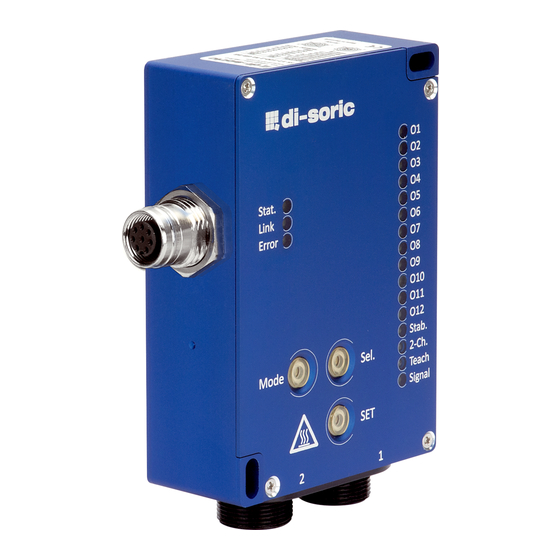
FS 12‐100‐1/2 M G8‐B8‐E Manual Displays Displays Table 14 : LED meaning LED Meaning O1‐O12 State output 1‐12 Stab. Error stabilization 2‐Ch. Two channel operation Teach Teach‐in mode active Signal Signal mode active Sel. Sensing channel 2 active SET Tolerance Stat., Link, Error Interface specific Table 15 : Assignment of flash impulses to tolerance values Flash impulses Tolerance Tolerance value 1 Very small 3 2 Small 6 3 Medium 9 4 Large 15 5 Very large ... -
Page 17: Button Operation
Button operation FS 12‐100‐1/2 M G8‐B8‐E Manual Button operation Automatic signal adjustment Position sensor to object Press "Mode" button shortly until "Sig." mode is active Press "SET" button for at least 2 seconds To store parameters press "Mode" button for at least 2 seconds Sample stabilization reference value Press "Mode" button shortly until "Sig." mode active Press "Sel." Button shortly to select stabilization channel Adjust signal level for stabilization channel mechanically (adjusting screw) Press "SET" button for at least 2 seconds To store parameters press "Mode" button for at least 2 seconds Teaching in colors Position sensor to object Press "Mode" button shortly until "Teach‐In" mode active Press "Sel." button to select table entry Press "SET" button for at least 2 seconds To store parameters press "Mode" button for at least 2 seconds Adjust tolerance Press "Mode" button shortly until "Teach‐In" mode active Press "SET" button shortly to select tolerance ... -
Page 18: Surge Protection
FS 12‐100‐1/2 M G8‐B8‐E Manual Surge protection Surge protection To use the sensor in systems where the supply voltage line > 3 meters, it is recommenced to use a filter module to protect against surges. A suitable 24 V DC filter module (surge) is available from the company WAGO under order number 750‐626. Page 18 di‐soric GmbH & Co. KG ... - Page 19 FS 12‐100‐1/2 M G8‐B8‐E Manual di‐soric GmbH & Co. KG Page 19 ...
Need help?
Do you have a question about the FS 12-100-1 M G8-B8-E and is the answer not in the manual?
Questions and answers