Table of Contents
Advertisement
Quick Links
INSTALLATION, OPERATION AND
MAINTENANCE MANUAL
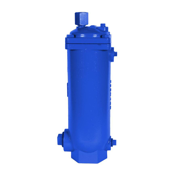
FIGURE 927
HIGH CAPACITY AIR RELEASE VALVES
FOR SEWAGE & WASTEWATER
TABLE OF CONTENTS
Introduction .................................. 2
................. 2
Receiving & Storage ....................... 2
Installation ..................................... 2
Valve Construction ......................... 3
Preventive Maintenance .................. 3
Testing/Trouble Shooting .................. 3
Disassembly .................................. 3
Assembly ...................................... 4
............... 4
Order Replacement Parts ................. 5
Repair Kits .................................... 5
Warranty ....................................... 5
Figure 927 Drawing/Parts List ........... 5
234 Clay Avenue • Mars, PA 16046 USA
Telephone (724) 776-1020 • Fax (724) 776-1254
E-mail:
info-ga@vag-group.com
Manual Number 927-IOM-110820 Rev A
Advertisement
Table of Contents

Related Manuals for Vag GA Industries FIGURE 927


Summary of Contents for Vag GA Industries FIGURE 927
-
Page 1: Table Of Contents
Order Replacement Parts …………….. 5 Repair Kits ……………………………… 5 Warranty .……………………………….. 5 Figure 927 Drawing/Parts List …….…. 5 234 Clay Avenue • Mars, PA 16046 USA Telephone (724) 776-1020 • Fax (724) 776-1254 E-mail: info-ga@vag-group.com Manual Number 927-IOM-110820 Rev A... -
Page 2: Introduction
INSTALLATION, OPERATION and MAINTENANCE Figure 927 Sewage Air Release Valves INTRODUCTION The valves should remain in a clean, dry and This manual will provide the information to weather protected area until installed. For long properly install, operate and maintain the valve term storage (greater than 6 months) the rubber to ensure a long service life. -
Page 3: Valve Construction
VAG/GA Industries air Disassemble the valve only as far as needed to valves with an “F” at the end of the Figure replace damaged or worn parts. -
Page 4: Assembly
bracket (3). The float and linkage will be free gently resting on the orifice (4). Secure by from the cover. tightening hex nut (8). Remove the hex nut (8) and lock washer (9) and Install valve links (14) and spring pins (13) to unscrew the orifice button (7) from the lever arm connect the float arm (12) to the lever arm (11). -
Page 5: Order Replacement Parts
• Close the inlet isolating valve and then REPLACEMENT PARTS slowly open the ½” flushing valve to Genuine replacement parts are available from your local VAG/GA Industries representative or relieve internal pressure. • Open the 1” blow off valve from the factory: •...
Need help?
Do you have a question about the GA Industries FIGURE 927 and is the answer not in the manual?
Questions and answers