Table of Contents
Advertisement
Quick Links
INSTALLATION, OPERATION AND
MAINTENANCE MANUAL
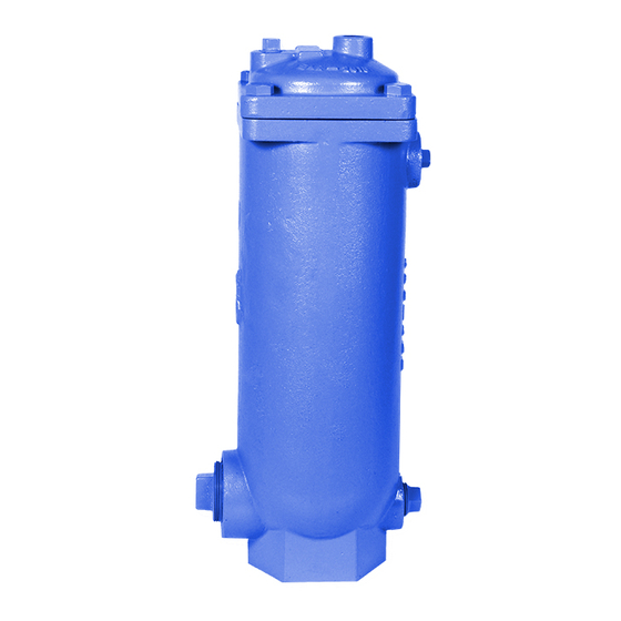
FIGURE 925
AIR RELEASE VALVES
FOR SEWAGE & WASTEWATER
TABLE OF CONTENTS
Introduction .................................. 2
................. 2
Receiving & Storage ....................... 2
Installation ..................................... 2
Valve Construction ......................... 3
Preventive Maintenance .................. 3
Testing/Trouble Shooting .................. 3
Disassembly .................................. 3
Assembly ...................................... 4
............... 4
Order Replacement Parts ................. 5
Repair Kits .................................... 5
Warranty ....................................... 5
Figure 925 Drawing/Parts List ........... 5
234 Clay Avenue • Mars, PA 16046 USA
Telephone (724) 776-1020 • Fax (724) 776-1254
E-mail:
info-ga@vag-group.com
Manual Number 925-IOM-111220
Advertisement
Table of Contents

Related Manuals for Vag GA INDUSTRIES FIGURE 925


Summary of Contents for Vag GA INDUSTRIES FIGURE 925
- Page 1 Backflushing Instructions Order Replacement Parts …………….. 5 Repair Kits ……………………………… 5 Warranty .……………………………….. 5 Figure 925 Drawing/Parts List …….…. 5 234 Clay Avenue • Mars, PA 16046 USA Telephone (724) 776-1020 • Fax (724) 776-1254 E-mail: info-ga@vag-group.com Manual Number 925-IOM-111220...
- Page 2 INSTALLATION, OPERATION and MAINTENANCE Figure 925 Sewage Air Release Valves INTRODUCTION The valves should remain in a clean, dry and This manual will provide the information to weather protected area until installed. For long properly install, operate and maintain the valve term storage (greater than 6 months) the rubber to ensure a long service life.
- Page 3 Disassemble the valve only as far as needed to facilitate such cleaning VAG/GA Industries air replace damaged or worn parts. valves with an “F” at the end of the Figure Number (e.g., 925F, 925LF) were supplied with...
- Page 4 (3). The float and linkage will be free from the float ball (20) and tighten. Apply Loctite 263 to cover. the threads on the other end of float rod. Install pivot link (15), lock washer (9) and hex nut (8) Remove the spring pins (13) connecting the on opposite end of float rod (19) and tighten.
- Page 5 REPLACEMENT PARTS REPAIR KITS Genuine replacement parts are available from Soft Goods Kit A925 (Part Number 2-80-11000- your local VAG/GA Industries representative or 008) contains Items 7, 8, 9 and 10 from the factory: Linkage Kit AL925 (Part Number 2-80-11000-...
Need help?
Do you have a question about the GA INDUSTRIES FIGURE 925 and is the answer not in the manual?
Questions and answers