Table of Contents
Advertisement
Quick Links
EV100
Electric Vehicle Supply Equipment
Tester
Operating Instructions
Bracken Hill
South West Industrial Estate
Peterlee
Co Durham
SR8 2SW
ENGLAND
Tel: +44(0)191 5863511
www.seaward.co.uk
sales@seaward.co.uk
service@seaward.co.uk
Part Number 405A566 Revision 1
September 2015
© 2015 Seaward Electronic
Advertisement
Table of Contents

Related Manuals for Seaward EV100


Summary of Contents for Seaward EV100
-
Page 1: Operating Instructions
EV100 Electric Vehicle Supply Equipment Tester Operating Instructions Bracken Hill South West Industrial Estate Peterlee Co Durham SR8 2SW ENGLAND Tel: +44(0)191 5863511 www.seaward.co.uk sales@seaward.co.uk service@seaward.co.uk Part Number 405A566 Revision 1 September 2015 © 2015 Seaward Electronic... -
Page 2: Table Of Contents
Single RCD trip time test 5.8.2 Automatic RCD test sequence Auto shutdown 5.10 Warning messages Seaward EVSEMobile App EVSEMobile functions Transferring data from the EV100 to EVSEMobile Adding photographs to a record Memory functions 6.4.1 PDF Export 6.4.2 Export all data 6.4.3 Import data 6.4.4... -
Page 3: Certificate Of Conformity
Performance: The instrument operates within specification when used under the conditions in the above standards EMC and Safety Standards. The product identified above conforms to the requirements of Council Directive 2004/108/EC and 2006/95/EC. Seaward Electronic Ltd is registered under BS EN ISO9001:2000 Certificate No: Q05356. - 3 -... -
Page 4: Limited Warranty And Limitation Of Liability
SEAWARD Electronic Limited. This also applies to accompanying drawings and diagrams. Due to a policy of continuous development SEAWARD Electronic Limited reserves the right to alter the equipment specification and description outlined in this publication without prior notice and no part of this publication shall be deemed to be part of any contract for the equipment unless specifically referred to as an inclusion within such contract. -
Page 5: Introduction
The EV100 is intended for use in a dry environment only. The EV100 may be used to make measurements on circuits rated up to CAT III 300 V AC/DC with reference to earth. Do not connect the EV100 to voltages that may exceed this rating. -
Page 6: Accessories
If the EV100 is used in a manner not specified by this document then the protection provided by the equipment may be impaired. -
Page 7: Using The Ev100
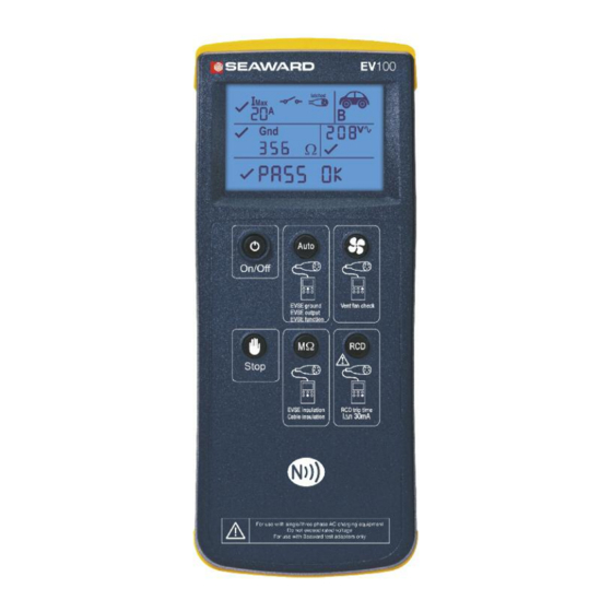
EVSE output voltage and phase 5 Using the EV100 5.1 Power On EV100 Press the ON/OFF key (2) to turn the EV100 on. Press and hold the ON/OFF key (2) for 2s to turn the EV100 off 5.2 Battery condition check The EV100 automatically performs battery condition checks whilst idle and during measurements. -
Page 8: Connecting The Ev100
5.3 Connecting the EV100 The EV100 can be used to simulate the presence of an Electric Vehicle (EV) connected to a charge point via a Type 1 or Type 2 tethered cable. Alternatively, in the case of an EVSE fitted with a Type 2 socket, the EV100 can simulate connection of an EV via a detachable charging cable with a rating of 13A, 20A, 32A or 70A by simulating the coding resistor that would be present in a cable of that rating. -
Page 9: Type 2 Direct Connection
NFC device and are available for transfer to the Seaward EVSEMobile App. 1. Connect the EV100 to the EVSE under test as described above in 5.3. 2. Press and release the Auto key (2) within 2s If the connection type is a Type 1 tethered cable, the •... -
Page 10: Extended Auto, Including Simulated Ev Faults
The EV100 will request charge current from the EVSE under test to drive it into state C. Note: The EV100 will wait for a period of 60s for a response from the EVSE. If the EVSE does not output a control pilot signal the EV100 will timeout and a warning message is displayed as shown in section 5.10... -
Page 11: Vented System Test
3. To proceed with the simulated EV faults, press the Auto key (3) or press the Stop key (4) to abort. • The EV100 will send a request for charge to drive the EVSE to state C, apply the following series of faults and measure the time taken for the EVSE to disconnect the supply to the output. -
Page 12: Rcd Test
1. Connect the EV100 to the EVSE under test as described above in 5.3. 2. Press the CCID test key (7). The EV100 will drive the EVSE into state C to energise the output and then apply a fault current •... -
Page 13: Auto Shutdown
The RCD should not trip during the 2s test and the EV100 display will show >2.00s • • The EV100 will display RCD (rated current RCD test) and apply a fault current of 30mA starting at 0°. The RCD should trip and the trip time is shown on the EV100 display. When the EV100 display •... - Page 14 There is no voltage present between phase and neutral or phase and earth when a request for charge is sent to the EVSE The internal EV100 fuse is blown, preventing the unit from performing earth loop impedance measurements on the EV100 supply. Check and replace the fuse as described in section 8.3...
-
Page 15: Seaward Evsemobile App
Android device must be removed and replaced on the front of the EV100 to initiate data transfer. • Place the Android device on top of the EV100 so that the NFC antenna in Android device if over the NFC logo on the EV100. - 15 -... -
Page 16: Adding Photographs To A Record
Operating Instructions If the location of the NFC antenna in the Android device is unknown, you may need to experiment by moving the Android device slowly around the top surface of the EV100. • Do not move the Android device during the data transfer. When the data has been successfully transferred, a message will appear on the Android display showing “Transfer... -
Page 17: Pdf Export
EV100 Operating Instructions 2. The complete database can be exported as a single zip file. The exported file contains all photographs and a single XML format data file containing all test data. The XML file can be opened with Microsoft Excel and the results data will automatically be sorted into headed columns. -
Page 18: Import Data
EV100 Operating Instructions Note: A monthly subscription is required to enable the premium features within EVSEMobile. This includes data import/export and generating PDF certificates. There are no restrictions on the amount of usage once an active subscription is in place. Follow the onscreen instruction to subscribe. -
Page 19: Specifications
EV100 Operating Instructions 7 Specifications 7.1 Insulation Resistance Display Range 0.01MΩ to 19.9MΩ Measurement Range 0.10MΩ to 19.9MΩ Accuracy +/- 5% +/- 5 digits Resolution 0.01MΩ maximum Open Circuit Test Voltage 500V dc -0% +20% Voltage Indication +/- 5% Test current >1mA into... -
Page 20: Maintenance
8.1 Cleaning Clean the external case of the EV100 and test adaptor with a clean dry cloth. Avoid using solvents and abrasive scouring agents to clean the external case of the EV100 or test adaptor. Check the battery contacts and compartment are free of electrolytic contamination. Any contamination of the battery contacts or compartment should be cleaned with a dry cloth. -
Page 21: Battery Replacement
EV100. Power the unit off and disconnect the test adaptor cable from the unit. Position the EV100 face down, undo the slotted captive screw in the battery compartment cover using a suitable tool and remove the battery compartment cover. - Page 22 EV100 Operating Instructions For help or advice on Service and Calibration contact: Service Department Seaward Electronic Bracken Hill South West Industrial Estate Peterlee Co Durham SR8 2SW England Tel: 0191 5878739 / 0191 5878737 Email: service@seaward.co.uk - 22 -...
-
Page 23: Appendix
EV100 Operating Instructions Appendix A EVSE simulation options Displayed message EV100 resistance Simulated EVSE connection Cable Tethered cable – Type 1 or Type 2 t2 70A 1k5 ohms ±1% Type 2 charging cable - 70A rated t2 32A 680 ohms ±1%...
Need help?
Do you have a question about the EV100 and is the answer not in the manual?
Questions and answers