Ecco K7000B Manual
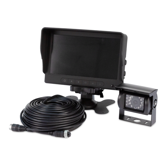
7 inch color camera system
Hide thumbs
Also See for K7000B:
- Installation instructions manual (13 pages) ,
- Installation instructions (5 pages)
Table of Contents
Advertisement
Available languages
Available languages
IMPORTANT! Read all instructions before installing and using. Installer: This manual must be delivered to the end user.
WARNING!
Failure to install or use this product according to manufacturer's recommendations may result in property damage, serious injury, and/
or death to those you are seeking to protect!
Do not install and/or operate this safety product unless you have read and understood the safety information
contained in this manual.
1.
Proper installation combined with operator training in the use, care, and maintenance of emergency warning devices are essential to
ensure the safety of emergency personnel and the public.
2.
Emergency warning devices often require high electrical voltages and/or currents. Exercise caution when working with live electrical
connections.
3.
This product must be properly grounded. Inadequate grounding and/or shorting of electrical connections can cause high current arcing,
which can cause personal injury and/or severe vehicle damage, including fire.
4.
Proper placement and installation is vital to the performance of this warning device. Install this product so that output performance of
the system is maximized and the controls are placed within convenient reach of the operator so that they can operate the system without
losing eye contact with the roadway.
5.
Do not install this product or route any wires in the deployment area of an air bag. Equipment mounted or located in an air bag
deployment area may reduce the effectiveness of the air bag or become a projectile that could cause serious personal injury or death.
Refer to the vehicle owner's manual for the air bag deployment area. It is the responsibility of the user/operator to determine a suitable
mounting location ensuring the safety of all passengers inside the vehicle particularly avoiding areas of potential head impact.
6.
It is the responsibility of the vehicle operator to ensure daily that all features of this product work correctly. In use, the vehicle operator
should ensure the projection of the warning signal is not blocked by vehicle components (i.e., open trunks or compartment doors),
people, vehicles or other obstructions.
7.
The use of this or any other warning device does not ensure all drivers can or will observe or react to an emergency warning signal.
Never take the right-of-way for granted. It is the vehicle operator's responsibility to be sure they can proceed safely before entering an
intersection, drive against traffic, respond at a high rate of speed, or walk on or around traffic lanes.
8.
This equipment is intended for use by authorized personnel only. The user is responsible for understanding and obeying all laws
regarding emergency warning devices. Therefore, the user should check all applicable city, state, and federal laws and regulations. The
manufacturer assumes no liability for any loss resulting from the use of this warning device.
CAUTION!
When drilling into any vehicle surface, make sure that the area is free from any electrical wires, fuel lines, vehicle upholstery, etc. that
could be damaged.
Notes:
1.
Larger wires and tight connections will provide longer service life for components. For high current wires it is highly recommended
that terminal blocks or soldered connections be used with shrink tubing to protect the connections. Do not use insulation displacement
connectors (e.g., 3M Scotchlock type connectors).
2.
Route wiring using grommets and sealant when passing through compartment walls. Minimize the number of splices to reduce voltage
drop. All wiring should conform to the minimum wire size and other recommendations of the manufacturer and be protected from moving
parts and hot surfaces. Looms, grommets, cable ties, and similar installation hardware should be used to anchor and protect all wiring.
3.
Fuses or circuit breakers should be located as close to the power takeoff points as possible and properly sized to protect the wiring and
devices.
4.
Particular attention should be paid to the location and method of making electrical connections and splices to protect these points from
corrosion and loss of conductivity.
5.
Ground termination should only be made to substantial chassis components, preferably directly to the vehicle battery.
6.
Circuit breakers are very sensitive to high temperatures and will "false trip" when mounted in hot environments or operated close to their
capacity.
Installation and Operation Instructions
7 Inch Color Camera System
Page 1 of 5
Advertisement
Table of Contents

Related Manuals for Ecco K7000B


Summary of Contents for Ecco K7000B
- Page 1 Installation and Operation Instructions 7 Inch Color Camera System IMPORTANT! Read all instructions before installing and using. Installer: This manual must be delivered to the end user. WARNING! Failure to install or use this product according to manufacturer’s recommendations may result in property damage, serious injury, and/ or death to those you are seeking to protect! Do not install and/or operate this safety product unless you have read and understood the safety information contained in this manual.
- Page 2 Installation, Wiring and Function Installation: Camera Model C2013B Important! Mount the camera at a location that provides the best view of the area immediately behind the vehicle. Generally, mounting locations toward the top of the vehicle provide the best field of view. Lower mounting locations reduce the field of view and increase the likelihood of damage from road spray.
- Page 3 Monitor: Model M7000B WARNING! To prevent accidental shock, DO NOT OPEN THE MONITOR CASE. Opening the monitor case will expose the inside of the monitor to conditions that could adversely affect performance. Any evidence of tampering with sealed components will void the warranty. Important! Do not expose the monitor to water, it is not waterproof.
- Page 4 Menu Operations: Use the touch button icon on the monitor or the Mode Select on the remote to adjust the viewing angle. Use the touch button icon on the monitor or the Menu Select on the remote. Click menu 7 times to switch between viewing angles using the arrow key.
-
Page 5: Replacement Parts
Truganina Victoria, Australia Seacroft, Leeds, England LS14 1FB +61 (0)3 8336 0680 +44 (0)113 2375340 800-635-5900 orders@eccogroup.com esgapsales@eccogroup.com esguk-code3@eccogroup.com ECCOESG.com ECCOESG.com/au/en ECCOESG.co.uk An ECCO SAFETY GROUP™ Brand ECCOSAFETYGROUP.com © 2021 ECCO, Inc. All rights reserved. 920-0929-00 Rev. D Page 5 of 5... - Page 6 Instrucciones de instalación Sistema de cámara color de 7 pulg. ¡IMPORTANTE! Lea todas las instrucciones antes de instalar y utilizar. Instalador: Este manual se debe entregar al usuario final. ¡ADVERTENCIA! Si no sigue las instrucciones del fabricante a la hora de instalar o usar el producto, pueden producirse daños materiales, y lesiones graves o incluso mortales a aquellos que pretende proteger! No instale ni opere este producto de seguridad, a menos que haya leído y comprendido la información de seguridad contenida en este manual.
- Page 7 Instalación, cableado y función: Instalación: Cámara modelo C2013B ¡Importante! Monte la cámara en la ubicación que proporcione la mejor vista del área inmediatamente detrás del vehículo. Por lo general, las ubicaciones de montaje hacia la parte superior del vehículo brindan el mejor campo de visión. Las ubicaciones de montaje inferiores reducen el campo de visión y aumentan la probabilidad de daños por rociado del camino.
- Page 8 Monitores: Modelos M7000B ¡ADVERTENCIA! Para evitar una descarga eléctrica accidental, NO ABRA LA CAJA DEL MONITOR. Al abrir la caja del monitor, el interior quedará expuesto a condiciones que podrían afectar el desempeño en forma adversa. Cualquier evidencia de alteración de los componentes sellados anulará la garantía. ¡Importante! No exponga el monitor al agua;...
- Page 9 Operaciones del menú Utilice el ícono del botón táctil en el monitor o "Mode Select" (Selección de modo) en el control remoto para ajustar el ángulo de visual- ización. Utilice el ícono de botón táctil en el monitor o el botón "Menu" (Menú) en el control remoto. Haga clic en el menú 7 veces para cambiar entre los ángulos de visión con la tecla de flecha.
-
Page 10: Replacement Part
Unit 1, Green Park, Coal Road Boise, Idaho 83705 Seacroft, Leeds, England LS14 1FB 800-635-5900 +44 (0)113 2375340 orders@eccogroup.com esguk-code3@eccogroup.com ECCOESG.com ECCOESG.co.uk An ECCO SAFETY GROUP™ Brand ECCOSAFETYGROUP.com © 2021 ECCO, Inc. Todos los derechos reservados. 920-0929-00 Rev. D Página 5 de 5... - Page 11 Instructions d'installation Système de caméra couleur 7 pouces IMPORTANT! Lisez toutes les instructions avant d’installer et d’utiliser le produit. Installateur : ce manuel doit être remis à l’utilisateur final. AVERTISSEMENT! Lisez toutes les instructions avant d’installer et d’utiliser le produit. Installateur : ce manuel doit être remis à l’utilisateur final. N’installez pas et/ou n’utilisez pas ce produit de sécurité...
- Page 12 Installation, câblage et fonctions: Installation: Modèle de caméra C2013B Important! Installez la caméra à l'endroit offrant le meilleur champ de vision possible sur la zone située immédiatement à l'arrière du véhicule. En général, ce sont les emplacements de montage situés vers le haut du véhicule qui fournissent le meilleur champ de vision possible.
- Page 13 Écrans : Modèles M7000B AVERTISSEMENT! Pour éviter les chocs accidentels, N'OUVREZ PAS LE BOÎTIER DU MONITEUR. Sinon, l'intérieur du moniteur sera exposé à des conditions pouvant nuire à son bon fonctionnement. Tout élément prouvant que les composants scellés ont été négligés annulera la garantie. Important! Ne mettez pas le moniteur en contact avec de l'eau car il n'est pas étanche.
- Page 14 À distance : Utilisez l’icône de touche tactile du moniteur ou la sélection de mode de la télécommande pour régler l’angle de visionnement. Utilisez l’icône de touche tactile du moniteur ou la sélection de mode de la télécommande. Cliquez 7 fois sur le menu pour passer d’un angle de visionnement à...
-
Page 15: Pièces De Rechange
Caractéristiques techniques : CAMÉRA C2013B MONITEUR M7000B Image CMOS Image 7 po. (4:3) et (16:9) Tension d’alimentation 12VCC Contrôleur 2 Caméra Pixels effectifs 976H x 592V Tension 12-24 Vcc Consommation d’énergie Consommation d’énergie Environ 5 W Objectif Taille 1/3”. Image en miroir Oui (via commutateur caméra et monit- eur) Angle d’objectif... - Page 16 Bâtiment A15, 5 Avenue Lionel Terray, Boise, Idaho 83705 Meyzieu, 69330, France 800-635-5900 +33 (0) 4 78 79 60 00 orders@eccogroup.com adv@esg.global ECCOESG.com ECCOESG.co.uk An ECCO SAFETY GROUP™ Brand ECCOSAFETYGROUP.com © 2021 ECCO, Inc. Tous droits réservés. 920-0929-00 Rev. D Page 6 sur 6...
-
Page 17: Installations- Und Bedienungsanleitung
Installations- und Bedienungsanleitung 7-Zoll-Farbkamerasystem WICHTIG! Lesen Sie vor der Installation und Verwendung alle Anweisungen. Monteur: Diese Anleitung muss dem Endbenutzer zugestellt werden. WARNUNG! Wenn Sie dieses Produkt nicht gemäß den Empfehlungen des Herstellers installieren oder verwenden, kann dies zu Sachschäden, schweren Personenschäden und/oder zum Tod für Sie und die Personen, denen Sie helfen möchten, führen! Installieren und/oder verwenden Sie dieses Sicherheitsprodukt nur, wenn Sie die Sicherheitsinformationen in dieser Anleitung gelesen und verstanden haben. - Page 18 Installation, Verdrahtung und Funktion Installation: Kameramodell C2013B Wichtig! Montieren Sie die Kamera an einem Ort, der optimale Sicht auf den Bereich direkt hinter dem Fahrzeug ermöglicht. Im Allgemeinen empfiehlt sich die Anbringung der Kamera oben am Fahrzeug, um ein gutes Sichtfeld zu erhalten. Wird die Kamera weiter unten angebracht, so verkleinert sich das Sichtfeld und die Wahrscheinlichkeit von Schäden durch Spritzer von der Fahrbahn erhöht sich.
- Page 19 Monitor: Modell M7000B WARNUNG! Um einen unabsichtlichen elektrischen Schock zu vermeiden, ÖFFNEN SIE DAS MONITORGEHÄUSE NICHT. Durch Öffnen des Monitorgehäuses wird das Innere des Monitors äußeren Einflüssen ausgesetzt, die sich negativ auf die Leistung auswirken können. Wenn Sie versiegelte Komponenten eigenmächtig manipulieren, erlischt die Garantie. Wichtig! Bringen Sie den Monitor nicht in Kontakt mit Wasser, da er nicht wasserdicht ist.
-
Page 20: Spezifikationen
Verwendung des Menüs: Über das Touch-Symbol auf dem Monitor und über die Modusauswahl auf der Fernbedienung können Sie den Blickwinkel ein- stellen. Verwenden Sie das Touch-Symbol auf dem Monitor oder die Menüauswahl auf der Fernbedienung. Klicken Sie 7 Mal auf „Menü“, um mit der Pfeiltaste zwischen den Blickwinkeln zu wechseln. - Page 21 833 West Diamond Street Riedweg 58-60, Boise, Idaho 83705 Ulm, 89081, Germany 800-635-5900 +49 731 935 210 orders@eccogroup.com ulm@eccogroup.com ECCOESG.com ECCOESG.co.uk An ECCO SAFETY GROUP™ Brand ECCOSAFETYGROUP.com © 2021 ECCO, Inc. Alle rechte vorbehalten. 920-0929-00 Rev. D Seite 5 von 5...
Need help?
Do you have a question about the K7000B and is the answer not in the manual?
Questions and answers