Table of Contents
Advertisement
Available languages
Available languages
Introduction:
ECCO's Reversing Camera System is designed to provide visual cues to help drivers avoid collisions
when backing up. A driver using a properly installed and maintained rear view system can be alerted
to potential safety hazards and thus take the appropriate action to prevent an accident. This manual
provides information about installation, function, safety, maintenance, replacement parts, and warranty.
!
WARNING!
Failure to install or use this product according to manufacturer's recommendations may result in property
damage, serious bodily/personal injury, and/or death to you and those you are seeking to protect!
Do not install and/or operate this safety product unless you have read and understand the
safety information contained in this manual.
1. Proper installation combined with operator training in the use, care, and maintenance of vehicle camera systems
are essential to ensure the safety of you and those you are trying to protect.
2. Exercise caution when working with live electrical connections.
3. This product must be properly grounded. Inadequate grounding and/or shorting of electrical connections can cause high
current arcing, which can cause personal injury and/or severe vehicle damage, including fire.
4. Proper placement and installation are vital to the performance of this device. Install this product so that output
performance of the system is maximized and the controls are placed within convenient reach of the operator so that
s/he can operate the system without losing eye contact with the roadway.
5. It is the responsibility of the vehicle operator to ensure during use that all features of this product work correctly. In use,
the vehicle operator should ensure the projection of the signal is not blocked by vehicle components (i.e., open
trunks or compartment doors), people, vehicles, or other obstructions.
!
WARNING!
1. High voltage is present within the monitor. The opening of the case should be by professionals.
2. Do not watch the video while driving unless you are monitoring the rear view camera display.
IMPORTANT!
Occasionally, a few highlights or dark spots may occur on the LCD screen. This is a very
common phenomenon in active matrix display technology, and doesn't necessarily indicate any defects or
faults. Never try to repair this device by yourself. In case of any problems, please turn off the display at once
and notify our company or authorized dealer. The monitor is a complex device. Any disassembly or modification
may lead to damage and void the warranty.
IMPORTANT!
The pedestal bracket ball joints can be tight when the system is new. These should be checked
before the camera is mounted to the windshield. Both ball joints should be firm but moveable by hand with
moderate effort. If necessary, lubricate each ball joint with silicone spray and work it in before installation. If
the mirror is adjusted and the ball joints are too tight, the windshield could crack.
Installation Instructions
Reversing Camera/Monitor System
Page 1 of 6
Advertisement
Table of Contents

Related Manuals for Ecco EC2015-C


Summary of Contents for Ecco EC2015-C
-
Page 1: Installation Instructions
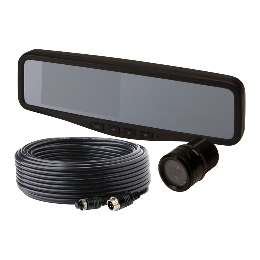
Reversing Camera/Monitor System Introduction: ECCO’s Reversing Camera System is designed to provide visual cues to help drivers avoid collisions when backing up. A driver using a properly installed and maintained rear view system can be alerted to potential safety hazards and thus take the appropriate action to prevent an accident. This manual provides information about installation, function, safety, maintenance, replacement parts, and warranty. - Page 2 CAMERA EC2015-C-Flush Mount MONITOR EC4204-M - 4.3” RV Mirror Image Color CMOS Image 4.3” LCD Color, 4:3 NTSC: 580*540 Controller Internal/2 camera PAL: 580*492 Voltage 12-24V Voltage Requirement 12V +/-1V Power Consumption Power Consumption < 1w Mirror Imaging Lens Angle 120°...
-
Page 3: Parts Identification
Accessories: 1. AV and power supply cable. 2. Center mount bracket. Parts Identification: Color LCD Screen Press to show menus or to Long press 3S to turn on/o select the lower setting the monitor. Short press to select Brightness decrease CAM channels. - Page 4 Menu: Press MENU to display the following options and settings: 1. Picture 2. Option 1. Picture: BRIGHT, CONTRAST, COLOR, AUTO DIM and SCALE ADJUST options will display on the screen as illustrated below: • Press M to select BRIGHT PICTURE BRIGHT CONTRAST COLOR...
-
Page 5: Troubleshooting
Camera is not installed parallel to the ground or camera is Adjust camera mounting bracket. if the Image Slanting rotated in its mounting location camera is an EC2015-C, ensure the red arrow sticker on the lens is pointing up after camera is installed and secured Declaration of conformity: This device complies with Part 15 of the FCC Rules. -
Page 6: Exclusion Of Other Warranties
Manufacturer Limited Warranty and Limitation of Liability: Manufacturer warrants that on the date of purchase this product will conform to Manufacturer’s specifications for this product (which are available from the Manufacturer upon request), and Manufacturer further warrants that this product is free from defects in materials and workmanship. - Page 7 Sistema de Monitor/Cámara de Reversa Introducción: El sistema de cámara de reversa ECCO está diseñado para brindar indicaciones visuales para que los conductores eviten los choques al retroceder con su vehículo. Un conductor que utiliza y mantiene el sistema de cámara retrovisora de manera adecuada puede recibir una alerta cuando existe un riesgo potencial de seguridad y, de este modo, tomar la decisión...
- Page 8 CÁMARA EC2015-C-Montaje empo- MONITOR EC4204-M - ESPEJO RV 4,3” trado Imagen 4,3” LCD de Color, 4:3 Imagen Color CMOS Controlador 2 cámaras internas NTSC: 580*540 Voltaje 12-24 V PAL: 580*492 Consumo de energía Demanda de voltaje 12 V +/-1 V Imagen por espejo Consumo de energía...
-
Page 9: Identificación De Partes
Accesorios: 1. Cable AV y de alimentación eléctrica. 2. Soporte de montaje central. Identificación de partes: Pantalla color LCD Color LCD Screen Presionar para mostrar el menú o para seleccionar Press to show menus or to Mantenga presionado 3S por Long press 3S to turn on/o la configuración más baja select the lower setting... - Page 10 Menú: Presione MENÚ para visualizar las siguientes opciones y configuraciones: 1. Imagen 2. Opción Imagen: Las opciones de BRILLO, CONTRASTE, COLOR, OSCURECIMIENTO AUTOMÁTICO y AJUSTE DE ESCALA se mostrarán en la pantalla, como se muestra a continuación: • Presione M para seleccionar BRILLO PICTURE BRIGHT CONTRAST...
-
Page 11: Resolución De Problemas
La cámara no está instalada en forma pralela al piso o la Ajuste la abrazadera de ensamblaje de la cámara se encuentra girada en su ubicación de ensamb- cámara. Si la cámara es una EC2015-C, laje asegúrese que el autoadhesivo de la flecha roja esté... -
Page 12: Limitación De La Responsabilidad
Garantía limitada del fabricante y limitación de la responsabilidad: El fabricante garantiza que, en la fecha de compra, este producto cumple con las especificaciones del fabricante para este producto (disponibles a solicitud del cliente). El fabricante también garantiza que este producto no posee ningún defecto en sus materiales o fabricación. -
Page 13: Instructions D'installation
Système Moniteur/Caméra de Recul Introduction : Le système de capteur de recul (Reversing Sensor System) d’ECCO donne des repères visuels pour éviter les collisions au moment de la marche arrière. Un conducteur utilisant un système de caméra de vision arrière correctement installé... - Page 14 CAMÉRA EC2015-C-Flush Mount MONITEUR EC4204-M - 4,3 po. RV Miroir Image Couleur CMOS Image 4,3 po. ACL couleur, 4:3 NTSC : 580*540 Contrôleur Interne/2 caméras PAL : 580*492 Tension 12 à 24 V Tension nécessaire 12 V +/-1 V Consommation d’électricité...
-
Page 15: Identification Des Pièces
Accessoires : 1. Câble AV et câble d’alimentation. 2. Support de montage central. Identification des pièces : Écran LCD couleur Color LCD Screen Appuyez pour afficher les menus ou pour sélectionner Press to show menus or to Appuyez longuement sur 3S pour Long press 3S to turn on/o le réglage inférieur select the lower setting... - Page 16 Menu : Appuyez sur MENU pour afficher les options et réglages suivants : 1. Image 2. Option Image : les options BRIGHT (LUMINOSITÉ), CONTRAST (CONTRASTE), COLOR (COULEUR), AUTO DIM (ATTÉNUATION AUTO), SCALE ADJUST (AJUSTEMENT ÉCHELLE) s’affichent à l’écran, comme indiqué ci-dessous : •...
-
Page 17: Dépannage
La caméra n'est pas installée parallèlement au sol ou la caméra est Régler le support de montage de tournée dans son emplacement de montage la caméra. S'il s'agit d'une caméra EC2015-C, assurez-vous que la flèche rouge autocollante sur l'objectif pointe vers le haut après l'installation et la fixation de la caméra... -
Page 18: Limitation De Responsabilité
Garantie limitée et limitation de responsabilité du fabricant : Le fabricant garantit qu’à la date d’achat ce produit sera conforme aux caractéristiques techniques définies par ses soins (disponibles sur demande) et qu’il est exempt de vices de fabrication et de main-d’œuvre. La présente garantie limitée est valable 1 an/12 mois à...
Need help?
Do you have a question about the EC2015-C and is the answer not in the manual?
Questions and answers