Advertisement
Available languages
Available languages
Quick Links
IMPORTANT!
Read all instructions before installing and using. Installer: This manual must be
delivered to the end user.
!
WARNING!
Failure to install or use this product according to manufacturers recommendations may result in property
damage, serious bodily/personal injury, and/or death to you and those you are seeking to protect!
Do not install and/or operate this safety product unless you have read and understand the safety
information contained in this manual.
1. Proper installation combined with operator training in the use, care, and maintenance of safety products are essential to ensure the
safety of you and those you are trying to protect.
2. Exercise caution when working with live electrical connections.
3. This product must be properly grounded. Inadequate grounding and/or shorting of electrical connections can cause high
current arcing, which can cause personal injury and/or severe vehicle damage, including fire.
4. Proper placement and installation are vital to the performance of this safety product. Install this product so that the
performance of the system is maximized and the controls are placed within convenient reach of the operator so that
s/he can operate the system without losing eye contact with the roadway.
5. It is the responsibility of the vehicle operator to ensure during use that all features of this product work correctly. In use,
the vehicle operator should ensure the field-of-view of the camera/monitor is not blocked by vehicle components (i.e., open
trunks or compartment doors), people, vehicles, or other obstructions.
6. Never take the right-of-way for granted. It is your responsibility to be sure you can proceed safely before entering an
intersection, driving against traffic, responding at a high rate of speed, walking on or around traffic lanes.
7. This equipment is intended for use by authorized personnel only. The user is responsible for understanding and
obeying all laws regarding safety products. Therefore, the user should check all applicable city, state, and federal laws and regula-
tions. The manufacturer assumes no liability for any loss resulting from the use of this safety product.
!
Caution! When drilling into any vehicle surface, make sure that the area is free from any electrical wires, fuel lines,
vehicle upholstery, etc. that could be damaged.
Notes:
1. Larger wires and tight connections will provide longer service life for components. For high current wires it is recommended
that terminal blocks or soldered connections be used with shrink tubing to protect the connections. Do not use insulation
displacement connectors (e.g., 3M Scotchlock type connectors)
2. Route wiring using grommets and sealant when passing through compartment walls. Minimize the number of splices to
reduce voltage drop. High ambient temperatures (e.g., under-hood) will significantly reduce the current carrying capacity of
wires, fuses, and circuit breakers. All wiring should conform to the minimum wire size and other recommendations of the
manufacturer and be protected from moving parts and hot surfaces. Looms, grommets, cable ties, and similar installation
hardware should be used to anchor and protect all wiring.
3. Fuses or circuit breakers should be located as close to the power takeoff points as possible and properly sized to protect the
wiring and devices.
4. Particular attention should be paid to the location and method of making electrical connections and splices to protect these
points from corrosion and loss of conductivity.
5. Ground termination should be only be made to substantial chassis components, preferably directly to the vehicle battery.
6. Circuit breakers are very sensitive to high temperatures and will "false trip" when mounted in hot enviroments or operated
close to their capacity.
Installation and Operation Instructions
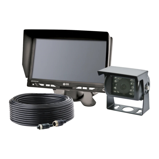
7 Inch Color Camera System
Page 1 of 16
Advertisement

Related Manuals for Ecco C2013B


Summary of Contents for Ecco C2013B
- Page 1 Installation and Operation Instructions 7 Inch Color Camera System IMPORTANT! Read all instructions before installing and using. Installer: This manual must be delivered to the end user. WARNING! Failure to install or use this product according to manufacturers recommendations may result in property damage, serious bodily/personal injury, and/or death to you and those you are seeking to protect! Do not install and/or operate this safety product unless you have read and understand the safety information contained in this manual.
- Page 2 Installation, Wiring and Function Installation: Camera Model C2013B Important! Mount the camera at a location that provides the best view of the area immediately behind the vehicle. Generally, mounting locations toward the top of the vehicle provide the best field of view. Lower mounting locations reduce the field of view and increase the likelihood of damage from road spray.
- Page 3 Monitor: Model M7000B WARNING! To prevent accidental shock, DO NOT OPEN THE MONITOR CASE. Opening the monitor case will expose the inside of the monitor to conditions that could adversely affect performance. Any evidence of tampering with sealed components will void the warranty. Important! Do not expose the monitor to water, it is not waterproof.
- Page 4 Trigger 1 timer (0-15 seconds) Zoom (16:9 or 4:3) ACC2 - Time Trigger 2 timer (0-15 seconds) Grid ON/OFF PRESET Sleep (0-240 mins) Specifications: CAMERA C2013B MONITOR M7000B Image CMOS Screen Size 7” (4:3) and (16:9) Voltage Requirement Controller 2 Camera Effective Pixels...
-
Page 5: Replacement Part
833 West Diamond St, Boise, Idaho 83705 Customer Service USA 800-635-5900 UK +44 (0)113 237 5340 | AUS +61 (0)3 63322444 ECCOESG.com An ECCO SAFETY GROUP™ Brand ECCOSAFETYGROUP.com 920-7700-00 Rev. F Page 5 of 16... - Page 6 Instrucciones de instalación Sistema de cámara color de 7 pulg. ¡IMPORTANTE! Lea todas las instrucciones antes de la instalación y el uso. Instalador: El presente manual debe entregarse al usuario final. ¡ADVERTENCIA! En caso de no instalar ni utilizar este producto conforme a las sugerencias del fabricante se podrían ocasionar daños a la propiedad, lesiones graves personales o el deceso del usuario y de las personas que se busca proteger.
- Page 7 Instalación, cableado y función: Instalación: Cámara modelo C2013B ¡Importante! Monte la cámara en la ubicación que proporcione la mejor vista del área inmediatamente detrás del vehículo. Por lo general, las ubicaciones de montaje hacia la parte superior del vehículo brindan el mejor campo de visión. Las ubicaciones de montaje inferiores reducen el campo de visión y aumentan la probabilidad de daños por rociado del camino.
- Page 8 Monitores: Modelos M7000B ¡ADVERTENCIA! Para evitar una descarga eléctrica accidental, NO ABRA LA CAJA DEL MONITOR. Al abrir la caja del monitor, el interior quedará expuesto a condiciones que podrían afectar el desempeño en forma adversa. Cualquier evidencia de alteración de los componentes sellados anulará la garantía. ¡Importante! No exponga el monitor al agua;...
- Page 9 Cronómetro del activador 1 (0 a 15 segundos) ACC2 - Tiempo Cronómetro del activador 2 (0 a 15 segundos) Grid ON/OFF AJUSTE PREESTABLECIDO Apagado automático (0 a 240 minutos) Specifications: CÁMARA C2013B MONITOR M7000B Imagen CMOS Tamaño de pantalla 7” (4:3) and (16:9) Requerimiento de voltaje Controlador 2 cámaras...
- Page 10 Algunas jurisdicciones no permiten la exclusión ni la limitación de daños incidentales o consecuenciales. 833 West Diamond St, Boise, Idaho 83705 Servicio Al Cliente EE.UU. 800-635-5900 Reino Unido +44 (0)113 237 5340 | AUS +61 (0)3 63322444 ECCOESG.com An ECCO SAFETY GROUP™ Brand ECCOSAFETYGROUP.com 920-7700-00 Rev. F Página 10 de 16...
- Page 11 Instructions d'installation Système de caméra couleur 7 pouces IMPORTANT! Avant d’installer et d’utiliser l’unité, lisez l’ensemble des instructions. Installateur : ce manuel doit être remis à l’utilisateur final. AVERTISSEMENT! Le non-respect des recommandations d’installation ou d’utilisation du fabricant peut entraîner des matériels, de graves blessures et/ou votre mort et celle de ceux que vous cherchez à...
- Page 12 Installation, câblage et fonctions: Installation: Modèle de caméra C2013B Important! Installez la caméra à l'endroit offrant le meilleur champ de vision possible sur la zone située immédiatement à l'arrière du véhicule. En général, ce sont les emplacements de montage situés vers le haut du véhicule qui fournissent le meilleur champ de vision possible.
- Page 13 Écrans : Modèles EC5603-M et EC7003-M AVERTISSEMENT! Pour éviter les chocs accidentels, N'OUVREZ PAS LE BOÎTIER DU MONITEUR. Sinon, l'intérieur du moniteur sera exposé à des conditions pouvant nuire à son bon fonctionnement. Tout élément prouvant que les composants scellés ont été négligés annulera la garantie. Important! Ne mettez pas le moniteur en contact avec de l'eau car il n'est pas étanche.
- Page 14 À distance : Augmentation Analogique Muet Allumer/éteindre Miroir Vertical/Image Miroir Horizontal/Image Normale Normale Volume Vers Le Bas Monter Le Son MENU Diminution Analogique Menu Mode (Standard, Vif, Doux, Temporisateur de veille MODE RESET TIMER Éclairage et Utilisateur) (0-240 mins) 16:9 Référence Inversant Commutation AV GRID...
-
Page 15: Caractéristiques Techniques
Caractéristiques techniques : CAMÉRA C2013B MONITEUR M7000B Image CMOS Image 7 po. (4:3) et (16:9) Tension d’alimentation 12Vcc Contrôleur 2 Caméra Pixels effectifs 725 x 488 Tension 12-24 Vcc Consommation d’énergie Consommation d’énergie Environ 5 W Objectif Taille 1/4 po. - Page 16 état à l’autre. Certains États n’autorisent pas l’exclusion ou la limitation de dommages indirects ou accessoires. 833 West Diamond St, Boise, Idaho 83705 Le Service Client États-Unis 800-635-5900 Royaume-Uni +44 (0)113 237 5340 | AUS +61 (0)3 63322444 ECCOESG.com An ECCO SAFETY GROUP™ Brand ECCOSAFETYGROUP.com 920-7700-00 Rév. F Page 16 sur 16...
Need help?
Do you have a question about the C2013B and is the answer not in the manual?
Questions and answers