Table of Contents
Advertisement
Available languages
Available languages
IMPORTANT! Read all instructions before installing and using. Installer: This manual must be delivered to the end user.
WARNING!
Failure to install or use this product according to manufacturer's recommendations may result in property damage, serious injury, and/
or death to those you are seeking to protect!
Do not install and/or operate this safety product unless you have read and understood the safety information
contained in this manual.
1.
Proper installation combined with operator training in the use, care, and maintenance of emergency warning devices are essential to
ensure the safety of emergency personnel and the public.
2.
Emergency warning devices often require high electrical voltages and/or currents. Exercise caution when working with live electrical
connections.
3.
This product must be properly grounded. Inadequate grounding and/or shorting of electrical connections can cause high current arcing,
which can cause personal injury and/or severe vehicle damage, including fire.
4.
Proper placement and installation is vital to the performance of this warning device. Install this product so that output performance of
the system is maximized and the controls are placed within convenient reach of the operator so that they can operate the system without
losing eye contact with the roadway.
5.
Do not install this product or route any wires in the deployment area of an air bag. Equipment mounted or located in an air bag
deployment area may reduce the effectiveness of the air bag or become a projectile that could cause serious personal injury or death.
Refer to the vehicle owner's manual for the air bag deployment area. It is the responsibility of the user/operator to determine a suitable
mounting location ensuring the safety of all passengers inside the vehicle particularly avoiding areas of potential head impact.
6.
It is the responsibility of the vehicle operator to ensure daily that all features of this product work correctly. In use, the vehicle operator
should ensure the projection of the warning signal is not blocked by vehicle components (i.e., open trunks or compartment doors),
people, vehicles or other obstructions.
7.
The use of this or any other warning device does not ensure all drivers can or will observe or react to an emergency warning signal.
Never take the right-of-way for granted. It is the vehicle operator's responsibility to be sure they can proceed safely before entering an
intersection, drive against traffic, respond at a high rate of speed, or walk on or around traffic lanes.
8.
This equipment is intended for use by authorized personnel only. The user is responsible for understanding and obeying all laws
regarding emergency warning devices. Therefore, the user should check all applicable city, state, and federal laws and regulations. The
manufacturer assumes no liability for any loss resulting from the use of this warning device.
CAUTION!
When drilling into any vehicle surface, make sure that the area is free from any electrical wires, fuel lines, vehicle upholstery, etc. that
could be damaged.
Notes:
1.
Larger wires and tight connections will provide longer service life for components. For high current wires it is highly recommended
that terminal blocks or soldered connections be used with shrink tubing to protect the connections. Do not use insulation displacement
connectors (e.g., 3M Scotchlock type connectors).
2.
Route wiring using grommets and sealant when passing through compartment walls. Minimize the number of splices to reduce voltage
drop. All wiring should conform to the minimum wire size and other recommendations of the manufacturer and be protected from moving
parts and hot surfaces. Looms, grommets, cable ties, and similar installation hardware should be used to anchor and protect all wiring.
3.
Fuses or circuit breakers should be located as close to the power takeoff points as possible and properly sized to protect the wiring and
devices.
4.
Particular attention should be paid to the location and method of making electrical connections and splices to protect these points from
corrosion and loss of conductivity.
5.
Ground termination should only be made to substantial chassis components, preferably directly to the vehicle battery.
6.
Circuit breakers are very sensitive to high temperatures and will "false trip" when mounted in hot environments or operated close to their
capacity.
CAUTION!
1. High voltage is present within the monitor. The opening of the case should be by professionals.
2. Do not watch the video while driving unless you are monitoring the rear view camera display.
Installation and Operation Instructions
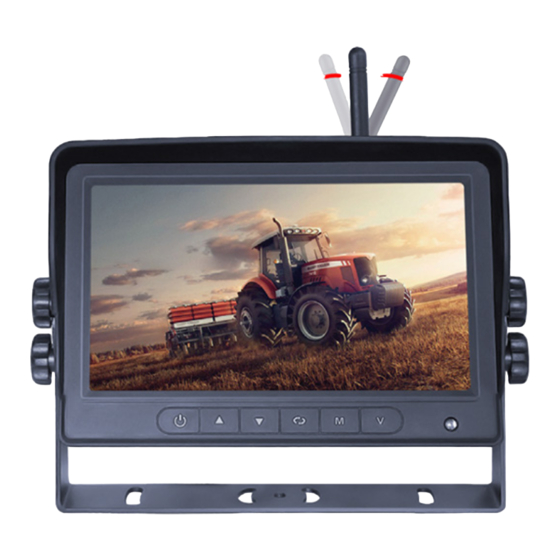
7-inch Wireless Color Camera System
Page 1 of 6
Advertisement
Table of Contents

Related Manuals for Ecco C2013B-WC


Summary of Contents for Ecco C2013B-WC
- Page 1 Installation and Operation Instructions 7-inch Wireless Color Camera System IMPORTANT! Read all instructions before installing and using. Installer: This manual must be delivered to the end user. WARNING! Failure to install or use this product according to manufacturer’s recommendations may result in property damage, serious injury, and/ or death to those you are seeking to protect! Do not install and/or operate this safety product unless you have read and understood the safety information contained in this manual.
-
Page 2: Installation And Mounting
Poor signal Figure 1 Camera Model C2013B-WC Installation Important! Mount the camera at a location that provides the best view of the area immediately behind the vehicle. Generally, Find an appropriate location for installation. -
Page 3: Menu Operations
Menu Operations Antenna Digital Color LCD Micro-SD / TF Card screen Slot Channel switch Power switch Menu SELECT Increase brightness Decrease brightness Audio On / Off Recording On / Off Figure 4 - Monitor Parts Turn on / off monitor and standby Increase brightness Decrease brightness Function1: OK... -
Page 4: Wiring Instructions
Wiring Instructions Important! Waterproof all connections whether inside or outside the vehicle by using sealant and wrapping with insulation tape. Wrap tape tightly, overlapping by one-half widths so there are no gaps. Camera Wiring This is the most commonly used method for users who have the single camera system (one moni- tor and one camera). -
Page 5: Menu Operation
Menu Operation Power Press Menu button to enter Menu interface. Press ▲/+ or ▼/- to select picture mode, press OK button to enter. Press ▲/+ or ▼/- and OK button to adjust BRIGHTNESS/CONTRAST/HUE/VOLUME. Mirror Press ▲/+ or ▼/- to select MIRROR setting, press OK to enter. Press ▲/+ or ▼/- and OK button to select NORMAL/MIRROR/FLIP/MIR-FLIP. -
Page 6: System Setting
Cam-setup Press ▲/+ or ▼/- and OK to enter CAM-SETUP, you can select the switch status, cycle time, and set automatic cycle of the four cam- eras. System Setting Get into the MENU interface, press ▲/+ or ▼/- and OK button to enter SYSTEM setting, under SYSTEM setting menu, you can adjust the DATE and TIME, LANGUAGE, NTSC/PAL SYSTEM, AUTO-DIM, DELAY/TIME, P-LINE. -
Page 7: Play Recorded File
Play Recorded File Recorded videos can be played by the monitor. Press ▲/+ or ▼/- and OK button to enter PLAY. Press ▲/+ or ▼/- and OK button to select and play a file. Press OK button to PLAY or PAUSE the file, press MENU key to exit. Rewrite and Format Get into RECORD interface, format SD card and loop recording function. -
Page 8: Troubleshooting
Troubleshooting The symptoms described below do not necessarily mean a failure in the display. Please check the following tiems before you initiate request for repair. Symptoms Possible Causes/Solutions No picture Improper connection of automobile adapter Use of unauthorized power supply Power switch is OFF Please re-pairing the system No signal... - Page 9 833 West Diamond St, Boise, Idaho 83705 Customer Service USA 800-635-5900 UK +44 (0)113 237 5340 | AUS +61 (0)3 63322444 ECCOESG.com An ECCO SAFETY GROUP™ Brand ECCOSAFETYGROUP.com © 2022 ECCO, Inc. All rights reserved. 920-0985-00 Rev. B Page 9 of 9...
- Page 10 Instrucciones de instalación y operación Sistema de cámara a color inalámbrica de 7 pulgadas ¡IMPORTANTE! Lea todas las instrucciones antes de instalar y utilizar. Instalador: Este manual se debe entregar al usuario final. ¡ADVERTENCIA! Si no sigue las instrucciones del fabricante a la hora de instalar o usar el producto, pueden producirse daños materiales, y lesiones graves o incluso mortales a aquellos que pretende proteger! No instale ni opere este producto de seguridad, a menos que haya leído y comprendido la información de seguridad contenida en este manual.
-
Page 11: Instalación Y Montaje
Señal débil Figura 1 Instalación de la cámara modelo C2013B-WC ¡Importante! Monte la cámara en el lugar que proporcione la mejor vista del área situada inmediatamente detrás del vehículo. Busque una ubicación apropiada para la instalación. -
Page 12: Operaciones Del Menú
Operaciones del menú Antena Pantalla LCD digital Ranura para tarjeta a color MicroSD o TF Interruptor de alimen- Cambio de canal tación Menú SELECCIONAR Encendido/apagado Aumentar brillo Disminuir brillo Encendido/apagado de grabación de audio Figura 4: Partes del monitor Encender/apagar monitor y modo de espera Aumentar brillo Disminuir brillo Función 1: aceptar... -
Page 13: Instrucciones De Cableado
Instrucciones de cableado ¡Importante! Impermeabilice todas las conexiones, ya sea dentro o fuera del vehículo, usando sellador y envolviéndolas con cinta aislante. Coloque la cinta firmemente y superpóngala por mitades del ancho para que no queden espacios. Cableado de la cámara Este es el método más utilizado por los usuarios que tienen el sistema de cámara individual (un monitor y una cámara). -
Page 14: Operación Del Menú
Operación del menú Encendido Presione el botón Menú para acceder a la interfaz de menú. Presione ▲/+ o ▼/- para seleccionar el modo de imagen, presione el botón Aceptar para ingresar. Presione ▲/+ o ▼/- y el botón Aceptar para ajustar el brillo (BRIGHTNESS), contraste (CONTRAST), tono (HUE) o volumen (VOLU- ME). -
Page 15: Configuración De Cámara
Configuración de cámara Presione ▲/+ o ▼/- y Aceptar para ingresar a la configuración de la cámara (CAM-SETUP). Puede seleccionar el estado del interruptor, el tiempo del ciclo y configurar el ciclo automático de las cuatro cámaras. Configuración del sistema Ingrese a la interfaz de MENÚ, presione ▲/+ o ▼/- y el botón Aceptar para ingresar a la configuración del sistema (SYSTEM). - Page 16 Reproducir archivo grabado El monitor puede reproducir los videos grabados. Presione ▲/+ o ▼/- y el botón Aceptar para seleccionar Reproducir (PLAY). Presione ▲/+ o ▼/- y el botón Aceptar para seleccionar y reproducir un archivo. Presione el botón Aceptar para reproducir o pausar el archivo, presione Menú para salir. Reescribir y formatear Ingrese a la interfaz de grabar (RECORD), formatee la tarjeta SD y active la función de grabación en bucle.
-
Page 17: Resolución De Problemas
Resolución de problemas Los síntomas descritos a continuación no necesariamente significan una falla en la pantalla. Verifique los siguientes elementos antes de iniciar la solicitud de reparación. Síntomas Posibles causas/soluciones No hay imagen Conexión incorrecta del adaptador del automóvil Uso de fuente de alimentación no autorizada El interruptor de alimentación está... - Page 18 Unit 1, Green Park, Coal Road Boise, Idaho 83705 Seacroft, Leeds, England LS14 1FB 800-635-5900 +44 (0)113 2375340 orders@eccogroup.com esguk-code3@eccogroup.com ECCOESG.com ECCOESG.co.uk An ECCO SAFETY GROUP™ Brand ECCOSAFETYGROUP.com © 2022 ECCO, Inc. Todos los derechos reservados. 920-0985-00 Rev. B Página 9 de 9...
- Page 19 Instructions d’installation et d’utilisation Système de caméra couleur sans fil de 7 pouces IMPORTANT! Lisez toutes les instructions avant d’installer et d’utiliser le produit. Installateur : ce manuel doit être remis à l’utilisateur final. AVERTISSEMENT! Le non-respect des recommandations du fabricant au cours de l’installation ou de l’utilisation de ce produit peut entraîner des dommages matériels et causer à...
-
Page 20: Installation Et Montage
Mauvais signal Figure 1 Installation de la caméra - Modèle C2013B-WC Important! Fixez la caméra à un endroit qui offre une meilleure visibilité de la zone située immédiatement derrière le véhicule. En Trouvez un emplacement approprié... -
Page 21: Opérations Du Menu
Opérations du menu Antenne Écran LCD couleur Fente pour carte numérique Micro-SD/TF Commutateur de Interrupteur d’alimen- canal tation SÉLECTIONNER Menu Augmenter la lumi- Diminuer la luminosité Enregistrement activé/ Audio activé/désactivé nosité désactivé Figure 4 - Pièces du moniteur Allumer/éteindre le moniteur et mettre en veille Augmenter la luminosité... - Page 22 Consignes de câblage Important! Imperméabilisez toutes les connexions à l’intérieur ou à l’extérieur du véhicule en utilisant du mastic et en enveloppant avec du ruban isolant. Enveloppez fermement le ruban, en le faisant se chevaucher d’une demi-largeur pour qu’il n’y ait pas d’espace. Câblage de la caméra Il s’agit de la méthode la plus couramment utilisée pour les utilisateurs disposant d’un système à...
- Page 23 Opération du menu Alimentation Appuyez sur le bouton Menu pour accéder à l’interface du menu. Appuyez sur les touches ▲/+ ou ▼/- pour sélectionner le mode image, appuyez sur le bouton OK pour y accéder. Appuyez sur les touches ▲/+ ou ▼/- et appuyez sur le bouton OK pour régler la LUMINOSITÉ/le CONTRASTE/la TEINTE/le VOLUME. Miroir Appuyez sur les touches ▲/+ ou ▼/- pour sélectionner le réglage MIROIR, appuyez sur le bouton OK pour y accéder.
-
Page 24: Configuration De La Caméra
Configuration de la caméra Appuyez sur les touches ▲/+ ou ▼/- et sur le bouton OK pour accéder à la fonction Configuration de la caméra; vous pouvez sélection- ner l’état du commutateur, la durée du cycle et définir le cycle automatique des quatre caméras. Paramètres système Accédez à... - Page 25 Lire le fichier enregistré Les vidéos enregistrées peuvent être lues par le moniteur. Appuyez sur les touches ▲/+ ou ▼/- et sur le bouton OK pour sélectionner PLAY (LIRE). Appuyez sur les touches ▲/+ ou ▼/- et sur le bouton OK pour sélectionner et lire un fichier. Appuyez sur le bouton OK pour LIRE ou PAUSE pour lire ou mettre en pause le fichier, appuyez sur la touche MENU pour quitter.
-
Page 26: Dépannage
Dépannage Les symptômes décrits ci-dessous ne signifient pas nécessairement une défaillance de l’affichage. Veuillez vérifier les éléments suivants avant de lancer une demande de réparation. Symptômes Causes/solutions possibles Pas d’image Mauvaise connexion de l’adaptateur automobile Utilisation d’une alimentation électrique non autorisée L’interrupteur d’alimentation est DÉSACTIVÉ... - Page 27 Bâtiment A15, 5 Avenue Lionel Terray, Boise, Idaho 83705 Meyzieu, 69330, France 800-635-5900 +33 (0) 4 78 79 60 00 orders@eccogroup.com adv@esg.global ECCOESG.com ECCOESG.co.uk An ECCO SAFETY GROUP™ Brand ECCOSAFETYGROUP.com © 2022 ECCO, Inc. Tous droits réservés. 920-0985-00 Rev. B Page 9 sur 9...
- Page 28 Installations- und Bedienungsanleitung Drahtloses 7-Zoll-Farbkamerasystem WICHTIG! Lesen Sie vor der Installation und Verwendung alle Anweisungen. Monteur: Diese Anleitung muss dem Endbenutzer zugestellt werden. WARNUNG! Wenn Sie dieses Produkt nicht gemäß den Empfehlungen des Herstellers installieren oder verwenden, kann dies zu Sachschäden, schweren Personenschäden und/oder zum Tod für Sie und die Personen, denen Sie helfen möchten, führen! Installieren und/oder verwenden Sie dieses Sicherheitsprodukt nur, wenn Sie die Sicherheitsinformationen in dieser Anleitung gelesen und verstanden haben.
-
Page 29: Installation Und Montage
Signalempfangsposition zu finden. Schlechter Empfang Abbildung 1 Installation des Kameramodells C2013B-WC Suchen Sie einen geeigneten Ort für die Installation. Bohren Sie Löcher entsprechend der Größe der U-Halterung und befestigen Sie sie. Bohren Sie ein 3/4 Zoll (19 mm) großes Loch neben der U-Halterung. - Page 30 Menüfunktionen Antenne Digitaler Farb-LCD- Micro-SD-/TF-Karten- Bildschirm steckplatz Kanalschalter Stromschalter Menü AUSWÄHLEN Helligkeit erhöhen Helligkeit verringern Audio ein/aus Aufnahme ein/aus Abbildung 4 – Monitorteile Monitor und Standby ein-/ausschalten Helligkeit erhöhen Helligkeit verringern Funktion 1: OK Funktion 2: Aufnahme starten/stoppen Funktion 3: Taste 3 Sekunden lang drücken, um die Parklinie ein-/ auszuschalten Funktion 1: Menü...
- Page 31 Verkabelungsanleitungen Wichtiger Hinweis! Sorgen Sie dafür, dass alle Verbindungen innerhalb und außerhalb des Fahrzeugs wasserdicht sind, indem Sie Dichtmittel und Isolierband verwenden. Umwickeln Sie das Klebeband fest und überlappen Sie es um eine halbe Breite, sodass keine Lücken entstehen. Kameraverkabelung Dies ist die am häufigsten verwendete Methode für Benutzer, die über ein Einzelkamerasystem (ein Monitor und eine Kamera) verfügen.
- Page 32 Menübedienung Leistung Drücken Sie die Menütaste, um die Menüoberfläche aufzurufen. Drücken Sie ▲/+ oder ▼/-, um den Bildmodus auszuwählen, und drücken Sie zum Aufrufen die OK-Taste. Drücken Sie ▲/+ oder ▼/- und die OK-Taste, um HELLIGKEIT/KONTRAST/FARBTON/LAUTSTÄRKE anzupassen. Spiegel Drücken Sie ▲/+ oder ▼/-, um die SPIEGEL-Einstellung auszuwählen, und drücken Sie zum Aufrufen OK. Drücken Sie ▲/+ oder ▼/- und die OK-Taste, um NORMAL/SPIEGEL/FLIP/SPIEGEL-FLIP auszuwählen.
- Page 33 Cam-Setup Drücken Sie ▲/+ oder ▼/- und OK, um CAM-SETUP aufzurufen. Sie können den Schaltstatus und die Zykluszeit auswählen und den automatischen Zyklus der vier Kameras einstellen. Systemeinstellung Rufen Sie die MENÜ-Schnittfläche auf, drücken Sie ▲/+ oder ▼/- und die OK-Taste, um die SYSTEM-Einstellung aufzurufen. Im SYS- TEM-Einstellungsmenü...
- Page 34 Aufgenommene Datei abspielen Aufgezeichnete Videos können über den Monitor abgespielt werden. Drücken Sie ▲/+ oder ▼/- und die OK-Taste, um die Wiedergabe aufzurufen. Drücken Sie ▲/+ oder ▼/- und die OK-Taste, um eine Datei auszuwählen und abzuspielen. Drücken Sie die OK-Taste, um die Datei abzuspielen oder anzuhalten, und drücken Sie die MENÜ-Taste, um den Vorgang zu beenden. Neu beschreiben (rewrite) und formatieren Rufen Sie die RECORD-Schnittstelle auf, formatieren Sie die SD-Karte und nutzen Sie die Loop-Aufnahmefunktion.
-
Page 35: Fehlerbehebung
Fehlerbehebung Die nachfolgend beschriebenen Symptome bedeuten nicht zwangsläufig einen Fehler im Display. Bitte überprüfen Sie den folgenden Zeitplan, bevor Sie eine Reparaturanfrage stellen. Symptome Mögliche Ursachen/Lösungen Kein Bild Falscher Anschluss des Kfz-Adapters. Verwendung einer nicht autorisierten Stromversorgung. Netzschalter ist AUS. Bitte koppeln Sie das System erneut. - Page 36 ECC0 (Hersteller) ECCO garantiert, dass dieses Produkt zum Zeitpunkt des Erwerbs den Spezifikationen von ECCO für dieses Produkt (auf Anfrage bei ECCO erhältlich) entspricht. Diese beschränkte Garantie gilt sechzig (60) Monate ab dem Zeitpunkt des Erwerbs. BEI SCHÄDEN AN TEILEN ODER PRODUKTEN, DIE DURCH MANIPULATION, UNFALL, MISSBRAUCH, UNSACHGEMÄSSE VERWENDUNG, FAHRLÄSSIGKEIT, NICHT GENEHMIGTE VERÄNDERUNGEN, FEUER ODER SONSTIGE GEFAHR;...
Need help?
Do you have a question about the C2013B-WC and is the answer not in the manual?
Questions and answers