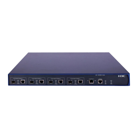
H3C WX5004 Installation Manual
Access controller
Hide thumbs
Also See for WX5004:
- Installation manual (85 pages) ,
- Quick start manual (11 pages) ,
- Configuration manual (64 pages)

Related Manuals for H3C WX5004


Summary of Contents for H3C WX5004
- Page 1 H3C WX5004 Access Controller Installation Guide Abstract This document details the procedures to install the WX5004 access controller. Hangzhou H3C Technologies Co., Ltd. http://www.h3c.com...
- Page 2 However, the statements, information, and recommendations in this document do not constitute a warranty of any kind, express or implied. Hangzhou H3C Technologies Co., Ltd. and its licensors shall not be liable for technical or editorial errors or omissions contained herein.
-
Page 3: Table Of Contents
Table of Contents 1 Product overview ··············································································································· 6 Introduction ································································································································· 6 Physical properties························································································································ 6 Front Panel ······························································································································ 6 Rear Panel ······························································································································ 7 2 Installation preparations ······································································································ 9 Unpacking and inspection ·········································································································· 10 Installation site examination ········································································································ 10 Laser safety ··························································································································· 10 Installation tools··························································································································... - Page 4 Power-on the access controller······························································································· 32 Software maintenance ··············································································································· 34 5 Support and other resources ······························································································35 Related documentation ············································································································· 35 Contacting H3C ························································································································· 35 Obtaining documentation ····································································································· 35 Technical support ·················································································································· 36 Documentation feedback ····································································································· 36 Document conventions and symbols ··························································································· 36 Conventions ··························································································································...
- Page 5 Cleanness requirements ········································································································· 51 Anti-static requirements ········································································································· 52 Electromagnetic environment requirements ············································································ 54 Index ···························································································································55...
-
Page 6: Product Overview
Hangzhou H3C Technologies Co., Ltd. (H3C) based on the updated multi-core CPU platform. Compared with the WX5002, the previous-generation access controller, the WX5004 has two more groups of combo ports, allowing for more flexible user configurations. The WX5004 also provides an expansion slot for future growth. -
Page 7: Rear Panel
(19) LED of the expansion card (20) LED of power supply 1 (21) LED of power supply 2 Rear Panel The WX5004 provides two power supply module slots and one expansion card slot (see Figure 3 Figure 3 Rear panel of the WX5004... - Page 8 (5) AC power socket of PSU 1 (6) PSU 2 (AC/DC) (7) Handle of PSU 2 (8) OPEN BOOK sign (9) Power cord retainer for PSU 2 (10) AC power socket of PSU 2 (11) Expansion card slot (12) OPEN BOOK sign (13) Grounding screw OPEN BOOK and CAUTION signs: Refer to related sections when performing the following operations:...
-
Page 9: Installation Preparations
Installation preparations WARNING! Installation and removal of the unit and its accessories must be carried out by qualified personnel. Read all of the Safety Instructions supplied with your device before installation and operation. WARNUNG! Installation und Ausbau der Anlage und ihrer Zubehörteile müssen von qualifiziertem Personal realisiert werden. -
Page 10: Unpacking And Inspection
If the package is found to be rusted or water soaked, stop unpacking and contact your H3C representative immediately. Installation site examination The WX5004 must be used indoors. You can mount the WX5004 in a cabinet or on a workbench. Make sure that: ... - Page 11 Phillips screwdriver: P2-150mm ESD-preventive wrist strap NOTE: Installation tools and ESD-preventive wrist strap are user-supplied.
-
Page 12: Installation
Installation CAUTION: If you are going to have an H3C agent maintain your access controller, ensure that the dismantlement-preventive seal on a mounting screw of the access controller chassis is intact. If you want to open the chassis, you should contact the agent for permission. Otherwise, you are responsible for consequences resulting from your actions. - Page 13 Figure 5 Rear mounting bracket appearance (1) Screw hole for fixing the rear mounting bracket to the rack (use M6 screws) (2) Heat dissipation hole Installation procedure Put on the EAD-preventive wrist strap and check that the rack is sturdy and properly grounded.
- Page 14 NOTE: There are three screw holes on both the right and left sides of the rear, and upper part of the access controller for installing the bearing screws. Locate the proper hole to install a bearing screw to each side. The rear mounting brackets can support the weight of the access controller through firm contact with the bearing screws.
- Page 15 Figure 9 Installation with front and rear mounting brackets (1) Front mounting bracket (2) Front square-hole rack rail (3) Bearing screw (4) Screw for fixing the rear mounting bracket to the rear square-hole rack rail (5) Rear mounting bracket (6) Rear square-hole rack rail After the access controller is pushed in, make sure that the upper side of the rear mounting brackets and the bearing screws are tightly connected (see Figure 10...
- Page 16 Figure 10 Installation with front and rear mounting brackets (1) Rear square-hole rack rail (2) Bearing screw (3) Rear mounting bracket Use screws and the corresponding cage nuts to fix the front mounting brackets to the front square-hole rack rails, so that the front and rear mounting brackets fix the access controller on the rack horizontally and steadily (see Figure 11...
-
Page 17: Installing The Access Controller With Front Mounting Brackets And A Tray
Figure 11 Installation with front and rear mounting brackets (1) Front square-hole rack rail (2) Front mounting bracket Installing the access controller with front mounting brackets and a tray NOTE: The tray is an optional component and must be separately ordered. Put on the EAD-preventive wrist strap and check that the rack is sturdy and properly grounded. -
Page 18: Installing The Access Controller With Mounting Brackets And Slide Rails
Slide rails are optional components, which need to be separately ordered if needed. H3C slide rails are suitable for only the H3C standard racks with a depth of 1000 mm (39.37 in.). If the depth of your rack is different, substitute other supports for the slide rails. - Page 19 Slide rail appearance Figure 2 Appearance of a slide rail (1) Slotted hole, a screw hole for fixing the slide rail to the rear round-hole rack rail of the rack. You can adjust the screw position within the screw hole according to the device position. (2) Heat dissipation hole.
- Page 20 Hold the two sides of the access controller with both hands, and then gently slide the access controller into a proper position on the rack (see Figure 4 Make sure that the bottom of the access controller touches the slide rails. Figure 4 Installation with front mounting brackets and slide rails NOTE:...
-
Page 21: Installing The Access Controller On A Workbench
Figure 5 Installation with front mounting brackets and slide rails (diagram callout) Installing the access controller on a workbench When a standard 19-inch rack is not available, you can install the access controller on a clean workbench. When installing the access controller on a workbench: ... - Page 22 The power input end of the access controller is connected with a noise filter, whose central ground is directly connected to the chassis, forming the chassis ground (also known as PGND). This chassis ground must be securely grounded so that induced and leaked electricity can be safely discharged to the ground, enhancing the anti-EMS capability of the access controller.
- Page 23 WARNING! The ground wire of the access controller should be connected to the grounding system in the equipment room. The fire main and lightning rod of a building are not good grounding options. When a grounding strip is unavailable If earth is available nearby and allows a grounding body to be buried, hammer an angle steel or steel pipe longer than 0.5 m (1.64 ft) into the earth.
-
Page 24: Connecting The Power Cord
Figure 8 Ground the access controller through an AC PE wire (1) Power transformer (2) AC power socket (3) Grounding terminal (4) Three-core AC power cord (5) PE wire Connecting the power cord WARNING! Make sure that the ground wire is properly connected before powering on the access controller. If the device is AC-powered, connect the device with an external AC power system through an AC power cord. -
Page 25: Connecting The Dc Power Cord
NOTE: Use the AC power cord retainer to prevent the AC power cord from accidentally falling off. Whether a power cord retainer is needed depends on the power supply system of the country. Figure 9 Install the AC power cord retainer (3) (4) (1) Rear panel (2) Power cord retainer slot... -
Page 26: Connecting Interface Cables
Figure 10 Connect the DC power cord Connecting interface cables Connecting the console cable Select a terminal for configuration. The terminal can be a character terminal with a standard RS232 serial port or a PC. A PC is used in this example. Connect the console cable. -
Page 27: Connecting The Ethernet Cable To An Ethernet Electrical Interface
Figure 11 Connect the console cable (1) RJ-45 connector (2) Console port (3) DB-9 (female) connector (4) Serial interface of the configuration terminal (5) Console cable NOTE: When connecting a PC to the access controller, first connect the DB-9 connector of the console cable to the PC, and then the RJ-45 connector to the console port of the access controller. - Page 28 The fiber ends are clean. Align the end of an SFP module without a handle with an SFP interface and carefully insert the SFP module into the SFP interface. Figure 12 Insert an SFP module Distinguish between the Rx and Tx interfaces on the SFP module. Connect the LC connector at one end of an optical fiber to the Rx interface of the access controller and the LC connector at the other end of the optical fiber to the Tx interface of the peer device.
-
Page 29: Checking The Installation
Figure 13 Plug LC connectors Power on the access controller and check the SFP interface LEDs. For description of SFP LED status, see ―LEDs‖ on page 43. Checking the installation After installation, make sure that: The correct power supply is used. ... -
Page 30: Initial Startup
Initial startup Setting up the configuration environment Connecting a configuration terminal to the access controller For information about connecting a configuration terminal to the access controller, see ―Connecting interface cables‖ on page 26. Setting terminal parameters Start the PC and run the terminal emulation program, such as the Terminal of Windows 3.1 or the HyperTerminal of Windows 95/98/NT/2000/XP. - Page 31 Figure 15 Select the serial interface used for HyperTerminal connection The system displays the port settings. Set Bits per second to 9600, Data bits to 8, Parity to None, Stop bits to 1, and Flow control to None. To use the default settings, click Restore Defaults.
-
Page 32: Powering On The Access Controller
The system displays the HyperTerminal interface. Select File > Properties > Settings in the HyperTerminal to enter the properties setting window. Select VT100 as the terminal emulation, and click OK. Figure 17 Set terminal emulation Powering on the access controller Check before power-on Before powering on the access controller, verify that: ... - Page 33 Done! ************************************************************************** H3C WX5004 BootWare, Version 1.06 ************************************************************************** Copyright (c) 2004-2009 Hangzhou H3C Technologies Co., Ltd. Compiled Date : Nov 9 2009 CPU Type : XLR716 CPU L1 Cache : 32KB CPU Clock Speed : 800MHz Memory Type : DDR2 SDRAM...
-
Page 34: Software Maintenance
Press Enter. The following prompt is displayed: <H3C> The prompt indicates that the system has entered user view and you can configure the access controller now. Software maintenance For WX5004 software maintenance information, see H3C WX Access Controller Software Maintenance Guide. -
Page 35: Support And Other Resources
WX series access controllers. Contacting H3C Obtaining documentation You can access the most up-to-date H3C product documentation on the World Wide Web at http://www.h3c.com. Click the links on the top navigation bar to obtain different categories of product documentation: Technical Support &... -
Page 36: Technical Support
Technical support customer_service@h3c.com http://www.h3c.com Documentation feedback You can e-mail your comments about product documentation to info@h3c.com. We appreciate your comments. Document conventions and symbols Conventions Convention Element Blue text: Table 24 Cross-reference links and email addresses Blue underlined text: Website addresses http://www.hp.com... -
Page 37: Symbols
Symbols WARNING! Indicates that failure to follow directions could result in bodily harm or death. CAUTION: Indicates that failure to follow directions could result in damage to equipment or data. IMPORTANT: Provides clarifying information or specific instructions. NOTE: Provides additional information. TIP: Provides helpful hints and shortcuts. -
Page 38: A Installation Of Lightning Arrester For Network Interfaces
A Installation of lightning arrester for network interfaces NOTE: You can install a lightning arrester for each 10/100 Mbps electrical Ethernet interface supporting RJ-45 connectors. A lightning arrester for network interface is not supplied with the access controller. When an outdoor network cable is attached to the access controller, to prevent possible damages to the access controller due to lightning strike, serially connect the lightning arrester for the network interface before you plug the outdoor cable into the... -
Page 39: Precautions
to the arrester while OUT end of the cable is connected to the access controller. After the connection, check whether the LEDs of the interface modules are normal. NOTE: Technical parameters, installation and maintenance methods of an arrester have been provided in the arrester instructions. - Page 40 lightning arrester for each of the network interfaces to guard the interfaces against possible damages.
-
Page 41: B Installation Of Lightning Arrester For Ac Power
B Installation of lightning arrester for AC power NOTE: A lightning arrester (lightning protection grounding strip) is not supplied with the access controller. If an outdoor AC power cable is directly led to the access controller, to prevent possible damages to the access controller due to lightning strike, serially connect the lightning arrester for AC power (lightning protection grounding strip) before you plug AC power cable into the access controller. - Page 42 Note the following: Make sure that the PE terminal of the arrester is well grounded before using the lightning arrester for power. Upon plugging the AC power cable connector of the access controller into the receptacle of the lightning arrester, if the green LED is on while the red LED does not alarm, it means that the lightning arrester of power is running and the function of lightning protection has taken effect.
-
Page 43: C Technical Specifications
C Technical specifications Components LEDs The WX5004 provides LEDs on the front panel (see Figure 20 Figure 20 LEDs of the WX5004 (1) 1000 Mbps LED of gigabit Ethernet interface (1000M) (2) System status LED (SYS) (3) Status LED of PSU 1 (PWR1) -
Page 44: Fixed Interfaces
The console cable is an 8-core cable. One end of the cable is a crimped RJ-45 connector and is connected to the console port of the WX5004. The other end is a DB-9 female connector and is connected to the 9-pin serial port on the configuration... - Page 45 → Ethernet interfaces The WX5004 provides four 10/100/1000 Base-T autosensing Ethernet electrical interfaces and four 1000 Base-X SFP optical interfaces. One electrical interface and one optical interface form a combo port, which is marked in a white box on the front panel. Only one interface (either electrical or optical) of a combo port can be used at a time.
- Page 46 A combo port supports optical-electrical automatic switching, however, when both the optical and electrical interfaces are connected, the electrical interface is used. SFP interface modules The WX5004 provides four SFP GE optical interfaces. The following SFP modules are available: ...
- Page 47 NOTE: No SFP module is shipped with the WX5004. You must purchase SFP modules as needed. H3C recommends using H3C SFP modules. RJ-45 connector The 10/100/1000 Mbps electrical Ethernet interfaces of the WX5004 use RJ-45 connectors to connect with the category 5 twisted pair cables (see Figure 22...
- Page 48 Figure 24 Ethernet cable RJ45 RJ45 Connector Connector Ethernet cables fall into the following two categories: Standard cable: Also called straight-through cable. At both ends of a standard cable, wires are crimped in the RJ-45 connectors in the same sequence. A straight-through cable is used to connect a terminal (for example, PC or router) to a Hub or LAN Switch.
-
Page 49: Fans
— Fans The WX5004 is equipped with five fans: three fans for heat dissipation of the main board and two fans for heat dissipation of the expansion card. If no expansion card is installed, these two fans do not work. -
Page 50: Dimensions And Weight
1 expansion card slot Slots 2 PSU slots Power input The WX5004 uses two AC/DC PSUs, which provide 1+1 redundancy backup for the WX5004 to enhance the system reliability. Table 11 AC/DC power input Item Description For AC power input: 100 VAC to 240 VAC, 50 Hz or 60 Hz Rated voltage range For DC power input: –48 VDC to –60 VDC... -
Page 51: Requirements On Temperature And Humidity
A high temperature is the most undesirable condition, because it accelerates the aging of insulation materials and thus significantly lowers the reliability and service life of the access controller. See Table 12 for temperature and humidity requirements for the WX5004. Table 12 Operating environment... -
Page 52: Anti-Static Requirements
0.01 Anti-static requirements Generation and damage of static electricity In the communication network to which the WX5004 is connected, static induction of the access controller mainly comes from the following sources: External electric fields, such as outdoor high-voltage transmission lines or thunderbolts. - Page 53 Wear ESD-preventive gloves or an ESD-preventive wrist strap and uniform when handling the circuit board. Hold the interface module only by its edge when installing, observing or removing it. Do not touch the components on it. Place the removed interface module on an ESD-preventive workbench with the component-side facing upward or place it in an antistatic bag.
-
Page 54: Electromagnetic Environment Requirements
Electromagnetic environment requirements The operation of your access controller may be affected by external interferences, such as capacitance coupling, inductance coupling, electromagnetic wave radiation, common impedance (including the grounding system) coupling, and the conducted interference of leads (power cords, signaling cables and output wires). To eliminate the interferences: ... -
Page 55: Index
44 configuration environment, 28 Connecting a configuration terminal, 28 heat dissipation, 19 console cable, 25, 42 humidity, 49 Console port, 42 Contacting H3C, 33 Conventions, 34 Crossover cable, 46 Initial startup, 28 Installation, 11 Installation site, 10 interface cables, 25... - Page 56 lightning arrester for network interfaces, 36 Related documentation, 33 RJ-45 connector, 45 Mounting bracket, 11 Setting terminal parameters, 28 SFP interface modules, 44 slots, 48 Software maintenance, 32 OPEN BOOK sign, 8 Standard cable, 46 Operating environment, 49 startup, 28 optical fibers, 26 static electricity, 50 optical interfaces, 44...
Need help?
Do you have a question about the WX5004 and is the answer not in the manual?
Questions and answers