
Related Manuals for H3C WBC580 G2


Summary of Contents for H3C WBC580 G2
- Page 1 H3C WBC580 G2 Multiservice Access Controller Installation Guide New H3C Technologies Co., Ltd. http://www.h3c.com Document version: 5W102-20211022...
- Page 2 The information in this document is subject to change without notice. All contents in this document, including statements, information, and recommendations, are believed to be accurate, but they are presented without warranty of any kind, express or implied. H3C shall not be liable for technical or editorial errors or omissions contained herein.
- Page 3 Preface This installation guide describes the procedure for installing an H3C WBC580 G2 multiservice access controller. This preface includes the following topics about the documentation: • Audience. • Conventions. • Documentation feedback. Audience This documentation is intended for: • Network planners.
- Page 4 Symbols Convention Description An alert that calls attention to important information that if not understood or followed WARNING! can result in personal injury. An alert that calls attention to important information that if not understood or followed CAUTION: can result in data loss, data corruption, or damage to hardware or software. An alert that calls attention to essential information.
- Page 5 Documentation feedback You can e-mail your comments about product documentation to info@h3c.com. We appreciate your comments.
-
Page 6: Table Of Contents
Contents 1 Preparing for installation ············································································· 1 Safety sign conventions ····································································································································· 1 Safety recommendations ··································································································································· 1 Safety symbols ··········································································································································· 1 General safety recommendations ·············································································································· 2 Electricity safety ········································································································································· 2 Laser safety ················································································································································ 3 Examining the installation site ···························································································································· 3 Temperature and humidity ························································································································· 3 Cleanliness ·················································································································································... - Page 7 Logging in to the license server ··············································································································· 16 Managing the Oasis platform ··························································································································· 17 Managing the AC ············································································································································· 19 Managing the license server ···························································································································· 21 Managing the device ········································································································································ 22 5 Maintenance ······························································································· 1 Guidelines ·························································································································································· 1 Maintenance tools ·············································································································································· 1 Maintenance operations ·····································································································································...
-
Page 8: Preparing For Installation
Table1-1 Safety signs Sign Description Circuit or electricity hazards are present. Only H3C authorized or professional device engineers are allowed to service, repair, or upgrade the device. WARNING! To avoid bodily injury or damage to circuits, do not open any components marked with the electrical hazard sign unless you have authorization to do so. -
Page 9: General Safety Recommendations
CAUTION means an alert that calls attention to important information that if not understood or followed can result in data loss, data corruption, or damage to hardware or software. General safety recommendations • Make sure the installation site is flat, vibration-free, and away from electromagnetic interferences. -
Page 10: Laser Safety
• Carefully examine your work area for possible hazards, such as moist floors. • Locate the emergency power-off switch in the room before installation. Shut off the power immediately if an accident occurs. Remove the power cord if necessary. • Do not work alone when you operate the device with power on. -
Page 11: Cleanliness
NOTE: The ventilation performance of the device depends on the installation density and ventilation in the rack. In a high-density environment, the available operating temperature might decrease. Cleanliness Dust buildup on the chassis might result in electrostatic adsorption, which causes poor contact of metal components and contact points, especially when indoor relative humidity is low. -
Page 12: Rack
Figure1-1 Airflow through the device Rack To rack-mount the device, make sure the rack meets the following requirements: • The rack is sturdy enough to support the weights of the device and its accessories. • The rack is grounded reliably. •... -
Page 13: Altitude
Altitude To ensure correct operation of the device, make sure the room altitude meets the requirements as described in Table1-6. Table1-6 Altitude requirements Item Description –60 m to +3000 m (–196.85 ft to +9842.52 ft) Operating altitude The allowed maximum temperature decreases by 0.33°C (32.59°F) as the altitude increases by 100 m (328.08 ft) from 900 m (2952.76 ft) Storage altitude –60 m to +5000 m (–196.85 ft to +16404.20 ft) -
Page 14: Installation Accessories
Installation accessories Figure1-2 Installation accessories Installation tools No installation tools are provided with the device. Prepare them yourself as required. Figure1-3 Installation tools Pre-installation checklist Table1-7 Pre-installation checklist Item Requirements Result • A minimum clearance of 10 cm (3.9 in) is reserved Installation around the chassis. - Page 15 Item Requirements Result Operating 5°C to 45°C (32°F to 113°F). temperature Operating humidity 8% RH to 90% RH, noncondensing • Dust concentration ≤ 3 x 10 particles/m Cleanliness • No visible dust on desk within three days. • The device is reliably grounded. •...
-
Page 16: Installing And Removing The Device
Keep the tamper-proof seal on a mounting screw on the chassis cover intact, and if you want to open the chassis, contact H3C for permission. Otherwise, H3C shall not be liable for any consequence. About the SL-2U-FR-S short rail kit The SL-2U-FR-S short rail kit shipped with the device includes left and right slide rails. - Page 17 Figure2-3 Left outer rail (1) Front mounting screw holes (2) Front mounting clip (3) Mounting bracket installation hole (4) Identification marks (5) Rear mounting clip (6) Rear mounting screw holes Figure2-4 Right outer rail (1) Front mounting screw holes (2) Front mounting clip (3) Mounting bracket installation hole (4) Identification marks (5) Rear mounting clip...
-
Page 18: Attaching Inner Rails To The Device
Figure2-5 Inner rail (1) Release tab (2) Keyhole slot Attaching inner rails to the device Unpack the inner rails. Pressing the release tab on the inner rail, extend each rail to its maximum length. Attach an inner rail to the device. IMPORTANT: For some devices, you must first remove the transport security screw before attaching inner rails to them. -
Page 19: Attaching Outer Rails To The Rack
Attaching outer rails to the rack Identify the left and right outer rails. Determine and mark the outer rail installation position on the rack posts. Make sure the rails take a 1U of rack space at the same height of the rack posts. Figure2-7 Correct and wrong installation positions As shown in Figure2-8, install two M6 cage nuts at the marked positions on each rear rack post. - Page 20 As a best practice, use a torque of 30 kgf·cm (2.94 Nm) to fasten the M6 countersunk head screws. Figure2-9 Securing the front end of an outer rail to the rack c. Adjust the length of the rail and attach the rear end of the outer rail to the rear rack post. As shown by callout 1 in Figure2-10, align the screw holes in the rear end of the outer rail with the cage nuts in the rear rack post and insert the mounting clip into the square hole in the rack post.
-
Page 21: Installing The Device In The Rack
Figure2-10 Securing the rear end of an outer rail to the rack Repeat the same procedure to attach the other outer rail to the rack. Make sure the left and right outer rails are installed at the same height so that the device can be installed safe and level on the rack. - Page 22 Figure2-12 Mounting the device in the rack Place the mounting brackets of the device flush against the front rack posts. Then use captive screws to secure the mounting brackets to the front rack posts. As a best practice, use a torque of 30 kgf·cm (2.94 Nm) to fasten the captive screws.
-
Page 23: Installing A Power Supply
Installing a power supply Remove the filler panel from the power supply slot. Figure2-14 Removing the filler panel from the power supply slot Push the power supply into the slot until it snaps into place. Figure2-15 Installing the power supply Connecting external cables Cabling guidelines WARNING! -
Page 24: Connecting A Mouse, Keyboard, And Monitor
Connecting a mouse, keyboard, and monitor Connect one plug of a VGA cable to a VGA connector on the device, and fasten the screws on the plug. Figure2-16 Connecting a VGA cable Connect the other plug of the VGA cable to the VGA connector on the monitor, and fasten the screws on the plug. -
Page 25: Connecting A Fiber Port
Figure2-18 Connecting an Ethernet cable Connecting a fiber port CAUTION: • To connect a fiber port by using an optical fiber, first install a transceiver module in the port and then connect the optical fiber to the transceiver module. • Insert a dust cap into any open optical fiber connector and a dust plug into any open fiber port or transceiver module port to protect them from contamination and ESD damage. -
Page 26: Connecting A Usb Device
Figure2-19 Connecting an optical fiber Examine the fiber port Link LED to verify that the port is operating correctly. For more information about the Link LED, see "Rear panel LEDs." Connecting a USB device USB devices are hot swappable. To connect a USB device: Connect the USB device to the USB connector, as shown in Figure2-20. -
Page 27: Connecting The Power Cord
Connecting the power cord WARNING! To avoid damage to the equipment or even bodily injury, use the power cord shipped with the device. Before connecting the power cord, make sure the device and components are installed correctly. To connect the power cord: Open the latch on the tie mount of the cable clamp and slide the clamp backward. -
Page 28: Removing A Power Supply
Figure2-22 Pressing the release tab Place the device on a clean, stable antistatic workbench or on the floor. Removing a power supply The power supplies are hot swappable. If two power supplies are installed and sufficient space is available for replacement, you can replace a power supply without powering off or removing the device from the rack. - Page 29 Figure2-24 Removing the power supply...
-
Page 30: Powering On And Powering Off The Device
Powering on and powering off the device Important information If the device is connected to external storage devices, make sure the device is the first device to power off and then the last device to power on. This restriction prevents the device from mistakenly identifying the external storage devices as faulty devices. -
Page 31: Procedure
Procedure Powering off the device from its operating system Connect a monitor, mouse, and keyboard to the device. Shut down the operating system of the device. Disconnect all power cords from the device. Powering off the device by pressing the power on/standby button Press and hold the power on/standby button until the system power LED turns into steady amber. -
Page 32: Logging In To The Device
Logging in to the device IMPORTANT: The information in this document might be slightly different depending on the software or hardware version of the device. The device uses the CentOS operating system and contains the following management components: • Cloud server (Oasis platform) —Allows users to monitor network conditions, manage the device, and operate O2O services online. -
Page 33: Logging In To The Device From Hdm
Know component IP addresses? Know WBC service Port IP address? Log in to HDM Log in to H3C WBC System Monitoring Platform License server Oasis platform Logging in to the device from HDM If you cannot obtain the IP addresses of the Oasis Platform, AC, license server, and WBC Monitoring Platform use this method to log in to the device. -
Page 34: Logging In To The Remote Console
Item Default setting Password (case-sensitive) Password@_ You can obtain the domain name from the label at the lower left corner on Domain name the chassis hood. Procedure Launch the browser, and enter the HDM management IP address in the https://hdm_ip_address format in the address bar. This example uses a Microsoft Internet Explorer browser and an HDM management IP address of 192.168.1.2. - Page 35 You can obtain the installation packages at the following websites: • Zulu OpenJDK: https://www.azul.com/downloads/zulu/ • IcedTea-Web: http://icedtea.wildebeest.org/download/icedtea-web-binaries/ To set up the Windows environment for KVM: Install the OpenJDK Java environment: a. Obtain the msi. installation file for Zulu OpenJDK and install OpenJDK with the default settings.
- Page 36 Setting up the Linux environment As a best practice, use Zulu OpenJDK 8 and IcedTea-Web to run HDM KVM. You can obtain the installation packages at the following websites: • Zulu OpenJDK: https://www.azul.com/downloads/zulu/ • IcedTea-Web: http://icedtea.wildebeest.org/download/source/ To set up the Linux environment for KVM: Install the IcedTea-Web plugin: Use the command to install the plugin.
- Page 37 Figure4-7 Running the HDM KVM The KVM login window opens. You can enter password admin.Default.0506 to access KVM. Launching a KVM or H5 KVM remote console Restrictions and guidelines Do not use KVM and H5 KVM at the same time or start the remote console in multiple browsers on one PC.
- Page 38 Procedure In the navigation pane, select Remote Services > Remote Console, as shown in Figure4-8. Figure4-8 Entering remote console page In the KVM or H5 KVM section, click a launch mode. This section launches an H5 KVM remote console. Encrypted modes transmit encrypted data and provide better security performance. Unencrypted modes transmit unencrypted data and provide higher transmission speed.
- Page 39 Figure4-10 Waiting for remote console access authorization If you are the primary user, you might need to grant access permissions to other users, as shown in Figure4-11. Figure4-11 Authorizing remote console access Parameters • Dedicated mode: Includes Encrypted dedicated mode and Unencrypted dedicated mode. A dedicated mode allows for only one remote console session and grants the user with the full access permission.
-
Page 40: Logging In To The Wbc Monitoring Platform
no other user is using the remote console. In the current software version, KVM supports only unencrypted dedicated mode. • Shared mode: Includes Encrypted shared mode and Unencrypted shared mode. A shared mode allows for a primary session and multiple secondary sessions. If you are the first access user, the system assigns you with the full access permission. - Page 41 Figure4-13 Oasis platform Web interface Figure4-14 AC Web interface...
- Page 42 Figure4-15 License server Web interface Click Manage at the right corner of the Oasis Platform, ACs, or License Server icon to access the O&M page. The Oasis platform O&M page, AC O&M page, and license server O&M page are as shown in Figure4-16, Figure4-17, and Figure4-18.
- Page 43 Figure4-16 Oasis platform O&M page Figure4-17 AC O&M page...
-
Page 44: Logging In To The Device From The Wbc Monitoring Platform
Figure4-18 license server O&M page Logging in to the device from the WBC Monitoring Platform If you can obtain only the URL of the WBC Monitoring Platform, use this method to log in to the device. In the Internet Explorer browser, enter the complete URL of the WBC Monitoring Platform in the format of https://IP:Port/zh-cn/login. - Page 45 Figure4-19 WBC Monitoring Platform login page Enter the username and password, and then click Log In. If this is the first login, enter the default username (admin) and password (admin.Default.0506). Figure4-20 WBC Monitoring Platform home page Click Oasis Platform, ACs, and License server to access the Oasis platform, AC, and license server Web interface, respectively.
-
Page 46: Logging In To The Device From A Local Pc
Logging in to the device from a local PC If you can obtain the IP addresses of the Oasis platform, AC, and license server, use this method to log in to the device. Logging in to the Oasis platform from the local PC Connect the PC to the device. -
Page 47: Logging In To The License Server
Logging in to the AC from the Web interface Connect the PC to the device. Launch the browser, and enter the AC IP address in the https://ip_address format in the address bar. This example uses a Microsoft Internet Explorer browser and an AC IP address of 192.168.100.155. -
Page 48: Managing The Oasis Platform
Figure4-23 License server login page Managing the Oasis platform Click Manage at the right corner of the Oasis Platform icon on the WBC Monitoring Platform to access the O&M page. The Oasis platform O&M page is as shown in Figure4-24. Figure4-24 Oasis platform O&M homepage Click the Logs tab, you can view the detailed logs and perform the following tasks: To delete a log file, you can right-click a log folder name and select Delete. - Page 49 Click the Update tab to update the Oasis platform version. Figure4-25 Oasis platform update page a. (Optional.) Click Upload. In the dialog box that opens, click Select File, select a file for upload, and then click Upload. After the file is uploaded to the Oasis platform, close the dialog box.
-
Page 50: Managing The Ac
Figure4-28 Oasis platform HA page a. Click Edit. b. To configure an HA scheduled task, click the icon to configure the backup interval and then click OK. The local device will back up the data to the remote device according to the specified backup interval. - Page 51 Figure4-30 AC O&M homepage Click the Logs tab, you can view the detailed logs and perform the following tasks: To delete a log file, you can right-click a log folder name and select Delete. To download logs, you can right-click a log folder name and select Download, or click ...
-
Page 52: Managing The License Server
Figure4-32 AC update page a. (Optional.) Click Upload. In the dialog box that opens, click Select File, select a file for upload, and then click Upload. After the file is uploaded to the AC, close the dialog box. Figure4-33 Uploading a file b. -
Page 53: Managing The Device
Figure4-35 License server O&M homepage Click the Logs tab, you can view the detailed logs and perform the following tasks: To delete a log file, you can right-click a log folder name and select Delete. To download logs, you can right-click a log folder name and select Download, or click ... - Page 54 Network Settings—Click Edit in the Network Settings area to modify the IPv4 address, mask, gateway, or DNS. Component Info—View the name and version number of each component. Port Info—View the port connection status. Health—View the device health status in real time, including overall health score, CPU ...
- Page 55 Figure4-38 Device logs page Click the Update tab to update the Device to the latest version, thus the device can use the latest features normally. Figure4-39 Device update page a. (Optional.) Click Upload. In the dialog box that opens, click Select File, select a file for upload, and then click Upload.
- Page 56 c. In the dialog box that opens, select an upgrade mode. The system version update will affect the service data. − If you select Uninstall and Upgrade, the system first Uninstall the current system version and then update the system version. During the Uninstallation and update process, the device logout occurs and the device login page displays.
- Page 57 Figure4-44 Uploading a backup file To roll back the history configuration, click Rollback History. You can then view and delete the rollback history records. Click the Security tab. Then you can configure the following parameters: Telnet—If you disable Telnet, you cannot log in to the device through Telnet to ensure the ...
-
Page 58: Maintenance
Maintenance The following information describes the guidelines and methods for daily device maintenance. Guidelines • Keep the equipment room where the device resides clean and tidy. Remove unnecessary devices or objects from the equipment room. • Make sure the temperature and humidity of the equipment room meet the device operating requirements. - Page 59 Checklist • The cable type is correct. • The cables are correctly and firmly connected and the cable length is appropriate. • The cables are in good condition and are not twisted or corroded at the connection point.
-
Page 60: Appendix A Chassis Views And Technical Specifications
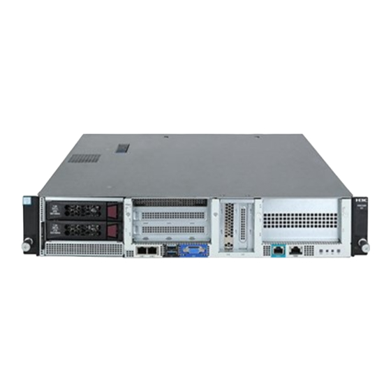
Appendix A Chassis views and technical specifications Chassis views Figure6-1 Front panel (1) 4TB drives (2) 1000BASE-T Ethernet ports (3) USB 2.0 connectors (4) SFP+ fiber ports (5) VGA connector (6) BIOS serial port (7) 1000BASE-T HDM dedicated network port (default IP address 192.168.1.2/24) Table6-1 Port and connector description Port or connector Connector type... -
Page 61: Technical Specifications
Figure6-2 Rear panel (1) Fan module slots (2) Power supply slots 1 and 2 Technical specifications Table6-2 Technical specifications Item Specifications Chassis height 1 U equals 44.45 mm (1.75 in) Dimensions (H × W × D) (excluding the mounting 87.5 × 440 × 451 mm (3.44 × 17.32 × 17.76 in) brackets) Weight (including two power supplies) 14 kg (30.86 lb) -
Page 62: Appendix B Leds
Appendix B LEDs Front panel LEDs Figure7-1 Front panel LEDs (1) Drive LEDs (upper: Fault/UID LED, lower: Present/Active LED) (2) 1000BASE-T port LEDs (3) SFP+ port LEDS (4) HDM dedicated network port LED (5) UID button/LED (6) Health LED (7) Power on/standby button and system power LED Table7-1 Drive LED description Fault/UID LED status Present/Active LED status... -
Page 63: Rear Panel Leds
Table7-3 Description for other LEDs and button Button/LED Status • Steady green—A link is present on the port. 1000Base-T Ethernet • Flashing green—The port is receiving or sending data. port LED • Off—No link is present on the port. • Steady green—A link is present on the port. - Page 64 Table7-4 LEDs and buttons on the rear panel Status • Steady green—The fan module is operating correctly. • Steady red—The fan module is faulty. Fan module status LED • Off—The fan module is not installed securely, or no power is present on the fan module.
-
Page 65: Appendix C Optional Transceiver Modules
Appendix C Optional transceiver modules Transceiver module, fiber connector, and optical fiber views The device provides SFP+ ports. To connect an SFP+ port on the device, use an SFP+ transceiver module and an optical fiber with LC connectors. Figure8-1 SFP transceiver module Figure8-2 SFP+ transceiver module Figure8-3 Optical fiber with LC connectors (1) LC connector... -
Page 66: Transceiver Module Specifications
Transceiver module specifications Table8-1 SFP-GE-LX-SM1310-A specifications Item Specification Central wavelength 1310 nm Max transmission distance 10 km (6.21 miles)/550 m (1804.46 ft) Transmission rate 1250 Mbps Connector type Duplex LC Fiber mode SMF/MMF 9 µm/50 μm (62.5 μm) Fiber diameter Transmit power –9.5 to –3 dBm ≤... - Page 67 Table8-4 SFP-XG-SX-MM850-E specifications Item Specification Central wavelength 850 nm Max transmission distance 300 m (984.25 ft) Transmission rate 10.3125 Gbps Connector type Duplex LC Fiber mode 50 μm/62.5 μm Fiber diameter Transmit power –7.3 to –1 dBm ≤ –9.9 dBm Receive sensitivity ≤...
Need help?
Do you have a question about the WBC580 G2 and is the answer not in the manual?
Questions and answers