Table of Contents
Advertisement
Advertisement
Table of Contents

Related Manuals for Orion XTR Subwoofers XTR102


Summary of Contents for Orion XTR Subwoofers XTR102
- Page 1 Subwoofer M O DE L XTR102 XTR104 XTR122 XTR124 XTR152 XTR154 OWNER'S MANUAL...
-
Page 2: Table Of Contents
Finding Speaker Mounting Locations ........ -
Page 3: Tools Of The Trade
ORION dealer for assistance. Orion dealers are trained professionals dedicated to extracting the maximum performance out of your Orion system. If you decide to install this speaker system yourself, please read the entire section on sealed and vented enclosures before starting the installation. -
Page 4: Features
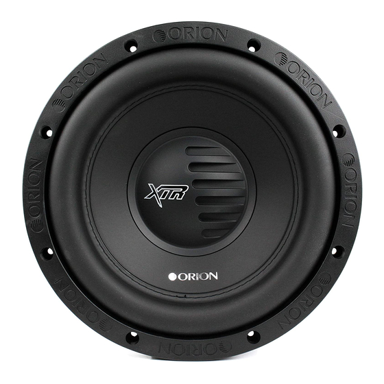
FEATURES Figure 1 Figura 1 Abbildung 1 Polypropylene dust cap - moisture and UV resistant. Oversized NBR (Nitrile-butadiene Rubber) surround for linear controlled long excursion. Paper cone - moisture and UV resistant. Custom stamped steel frame. Vented Aluminum voice coil former (2.5" voice coil former). 8mm steel front plate. -
Page 5: Wiring Configurations
Figura 3 Abbildung 3 1. Connect the speaker in parallel by connecting the two positive (+) terminals together and the two negative (-) terminals together. 2. Wire the positive (+) terminals of the woofer to the positive (+) terminal on the amplifier. - Page 6 Figura 4 Abbildung 4 1. Connect the speaker in parallel by connecting the two positive (+) terminals together and the two negative (-) terminals together. 2. Wire both positive (+) terminals of the woofer to the positive (+) terminal on the amplifier.
- Page 7 Figura 5 Abbildung 5 1. Connect the speaker in parallel by connecting the four positive (+) terminals together and the four negative (-) terminals together. 2. Wire the positive (+) terminals of the woofers to the positive (+) terminal on the amplifier.
- Page 8 Series/Parallel - Two Speakers (dual 2 ohm voice coils) Note: Verify and ensure that the woofer wiring is connected as shown with the negative connection from the first woofer coil connected to the positive connection of the second woofer coil. Two dual 2 ohm voice coil woofers with voice coils in series and then parallel the two series woofers results in a 2 ohm load to the amplifier.
- Page 9 Series/Parallel - Three Speakers (dual 4 ohm voice coils) Note: Verify and ensure that the woofer wiring is connected as shown with the negative connection from the first woofer coil connected to the positive connection of the second woofer coil. Three dual 4 ohm voice coil woofer with voice coils of each woofer wired in series and then parallel the three woofers for a resulting 2.67 ohm load to the amplifier.
- Page 10 Series/Parallel - Three Speakers (dual 2 ohm voice coils) Note: Verify and ensure that the woofer wiring is connected as shown with the negative connection from the first woofer coil connected to the positive connection of the second woofer coil. Three dual 2 ohm voice coil woofer with voice coils of each woofer wired in series and then parallel the three woofers for a resulting 1.33 ohm load to the amplifier.
- Page 11 Series/Parallel - Four Speakers (dual 4 ohm voice coils) Note: Verify and ensure that the woofer wiring is connected as shown with the negative connection from the first woofer coil connected to the positive connection of the second woofer coil. Four dual 4 ohm voice coil woofers should be wired with the voice coils on each woofer in series and then parallel the four woofers for a resulting 2 ohm load to the amplifier.
- Page 12 Series/Parallel - Four Speakers (dual 2 ohm voice coils) Note: Verify and ensure that the woofer wiring is connected as shown with the negative connection from the first woofer coil connected to the positive connection of the second woofer coil. Four dual 2 ohm voice coil woofers should be wired with the voice coils on each woofer in series and then parallel the four woofers for a resulting 1 ohm load to the amplifier...
- Page 13 Figura 11 Abbildung 11 1. Connect one of the speaker’s voice coils to the first amplifier by connecting the positive (+) terminal and the negative (-) terminal from the speaker to the respective positive (+) terminal and the negative (-) terminal from the first amplifier.
- Page 14 Figura 12 Abbildung 12 1. Connect one of the speaker’s voice coils to the first amplifier by connecting the positive (+) terminal and the negative (-) terminal from the speaker to the respective positive (+) terminal and the negative (-) terminal from the first amplifier.
-
Page 15: Specifications
Sd (effective radiating area, sq. cm.) Sd (effective radiating area, sq. in.) Frequency range (Hz) Energy Bandwidth Product (EBP) ** Driver Physical Dimension Speaker Displacement (cu ft) Speaker Outer Diameter (inches/mm) Mounting hole diameter (inches/mm) Mounting depth (inches/mm) Magnet Weight (Oz) - Page 16 Sd (effective radiating area, sq. cm.) Sd (effective radiating area, sq. in.) Frequency range (Hz) Energy Bandwidth Product (EBP) ** Driver Physical Dimension Speaker Displacement (cu ft) Speaker Outer Diameter (inches/mm) Mounting hole diameter (inches/mm) Mounting depth (inches/mm) Magnet Weight (Oz)
- Page 17 At least 0.75" MDF (Medium Density Fiberboard) is recommend for any XTR enclosure. Recommended enclosures are NET box volumes, speaker and port displacement are calculated into the volume of the enclosure, you will not need to add these volumes to calculate GROSS volume for the enclosure.
-
Page 18: Explanation Of Enclosure Specifications
The size of the enclosure is directly proportional to the efficiency and power handling of that speaker. A woofer in a smaller enclosure will handle more power than the same woofer in a larger enclosure. The exact opposite is true for efficiency, a larger enclosure will play lower frequencies at a louder volume with less power than a smaller enclosure. -
Page 19: Enclosure Recommendations
ENCLOSURE RECOMMENDATIONS Enclosure Details 1. External dimensions calculated for 3/4” building material 2. Includes speaker displacement 3. Volumes given are net tuning volume 4. Enclosures include a minimal amount of damping material. Just enough material to line the inside of the enclosure is required. - Page 20 XTR102 & 104 Vented Enclosure Recommendations Box Properties — Description — Type: Vented Box Shape: Prism, Square Figure 15 Figura 15 Abbildung 15 Top & Bottom Front & Back © 2008 directed electronics—all rights reserved — Box Parameters — 1 cu.ft V(total) = 1.111 cu.ft 40 Hz...
- Page 21 XTR122 & 124 Sealed Enclosure Recommendations Box Properties — Description — Type: Closed Box Shape: Prism, Square Top & Bottom Front & Back Figure 16 Figura 16 Abbildung 16 — Box Parameters — V(total) = Fill External Dimensions A = 16 in. (406 mm) B = 16 in.
- Page 22 XTR122 & 124 Vented Enclosure Recommendations Box Properties — Description — Type: Vented Box Shape: Prism, Square Figure 17 Figura 17 Abbildung 17 Top & Bottom Front & Back © 2008 directed electronics—all rights reserved — Box Parameters — 1.5 cu.ft V(total) = 1.705 cu.ft 40 Hz...
- Page 23 XTR152 & 154 Sealed Enclosure Recommendations Box Properties — Description — Type: Closed Box Shape: Prism, Square Top & Bottom Front & Back Figure 18 Figura 18 Abbildung 18 — Box Parameters — V(total) = Fill External Dimensions A = 17.5 in. (445 mm) B = 17.5 in.
- Page 24 XTR152 & 154 Vented Enclosure Recommendations Box Properties — Description — Type: Vented Box Shape: Prism, Square Figure 19 Figura 19 Abbildung 19 Top & Bottom Front & Back © 2008 directed electronics—all rights reserved — Box Parameters — 3 cu.ft V(total) = 3.247 cu.ft 36 Hz...
-
Page 25: Français
FRANÇAIS INSTALLATION Les performances de ces haut-parleurs de graves XTR sont directement liées à la qualité de l’installation. Les précautions prises lors de l’installation se traduiront par des années de bon fonctionnement. Si vous doutez de pouvoir obtenir une bonne installation, veuillez demander l’assistance technique d’un revendeur Orion agréé. - Page 26 CARACTÉRISTIQUES Calotte pare-poussière en polypropylène, résistante à l’humidité et aux UV. Suspension surdimensionnée en caoutchouc nitrile-butadiène permettant une longue course contrôlée. Cône papier – résistant à l’humidité et aux UV. Cadre sur mesure en acier matricé Corps de bobine mobile en aluminium avec évents (corps de bobine mobile de 2,5”).
- Page 27 CONFIGURATIONS DE CÂBLAGE Série – Un haut-parleur (deux bobines mobiles de 2 ohms) Voir la figure 2 à la page 4 Un haut-parleur de graves à deux bobines mobiles de 2 ohms raccordées en série constitue une charge de 4 ohms pour l’amplificateur. 1.
- Page 28 (+) de l’amplificateur. Raccordez les bornes négatives (-) des haut-parleurs de graves à la borne négative (-) de l’amplificateur. Série-parallèle – Deux haut-parleurs (deux bobines mobiles de 2 ohms) Voir la figure 6 à la page 7 Remarque : Vérifiez que le câblage du haut-parleur de graves est conforme à l’illustration, avec la borne négative de la première bobine du haut-parleur de graves reliée à...
- Page 29 1. Configurez chaque haut-parleur de graves en série en raccordant la borne négative (-) de la première bobine à la borne positive (+) de la seconde. 2. Raccordez la borne positive (+) de la première bobine de chaque haut-parleur de graves à...
- Page 30 (+) et négative (-) correspondantes du premier amplificateur. 2. Raccordez l’autre bobine mobile du haut-parleur au second amplificateur en reliant les bornes positive (+) et négative (-) du haut-parleur aux bornes positive (+) et négative (-) correspondantes du second amplificateur. 2 amplificateurs –...
- Page 31 Sd (surface effective de rayonnement, pouces-carrés) Plage de fréquence (Hz) Facteur d’efficacité (EBP) ** Encombrement du haut-parleur Volume du haut-parleur (pieds-cubes) Diamètre extérieur du haut-parleur (pouces/mm) Diamètre du trou de montage (pouces/mm) Profondeur de montage (pouces/mm) Poids de l’aimant (onces) Diamètre du saladier (pouces/mm) Caissons recommandés Caisson clos courant (pieds-cubes)
- Page 32 EXPLICATION DES CARACTÉRISTIQUES TECHNIQUES DES CAISSONS De nombreux facteurs entrent en jeu dans la détermination du meilleur type de caisson pour un utilisateur ou un véhicule donné. Voici quelques uns de ces facteurs. La taille du caisson est directement proportionnelle au rendement et à la puissance admissible du haut-parleur.
- Page 33 RECOMMANDATIONS SUR LES ENCEINTES Détails des enceintes 1. Dimensions externes calculées pour des matériaux de 3/4” 2. Inclut le volume d'encombrement des haut-parleurs 3. Les volumes indiqués sont le volume d'accord net 4. Les enceintes contiennent une quantité minimale de matériaux d'amortissement. Il suffi...
- Page 34 Explication des diagrammes de caissons à évent accordé (voir les dimensions en pages 19, 21 et 23) Propriétés du caisson — Description — Type : Caisson à évent accordé Forme : Prisme, carré Haut et Avant et arrière — Paramètres du caisson — V(total) Remplissage —...
-
Page 35: Español
ESPAÑOL INSTALACIÓN El rendimiento de estos subwoofers XTR es directamente proporcional a la calidad de la instalación. El cuidado que se tenga durante el proceso de instalación será recompensado con muchos años de rendimiento satisfactorio. Si no está seguro de sus capacidades de instalación, pídale asistencia técnica al distribuidor autorizado local de Orion. - Page 36 CARACTERÍSTICAS Tapa de polipropileno contra el polvo; resistente a la humedad y a los rayos ultravioleta. Envolvente de Goma de Butadieno de Nitrilo (NBR) para grandes desplazamientos lineales controlados. Cono de papel resistente a la humedad y los rayos ultravioleta. Armazón de acero troquelado a la medida.
- Page 37 CONFIGURACIONES DE CABLEADO En serie: un altavoz (dos bobinas acústicas de 2 Ω) Vea la figura 2 en la página 4 Un woofer con dos bobinas acústicas de 2 Ω y las bobinas acústicas en serie produce una carga de 4 Ω en el amplificador. 1.
- Page 38 negativa (-) del amplificador. En serie/paralelo: dos altavoces (dos bobinas acústicas de 2 Ω cada uno) Vea la figura 6 en la página 7 Nota: Verifique y asegúrese de que el cableado del woofer es como se muestra: la terminal negativa de la bobina de un woofer conectada a la terminal positiva de la bobina del otro woofer.
- Page 39 Vea la figura 9 en la página 10 Nota: Verifique y asegúrese de que el cableado del woofer es como se muestra: la terminal negativa de la bobina de un woofer conectada a la terminal positiva de la bobina del otro woofer. Cuatro woofers con dos bobinas acústicas de 4 Ω...
- Page 40 amplificador produce una carga de 4 Ω en cada amplificador. 1. Conecte la terminal positiva (+) y la terminal negativa (-) de una de las bobinas del altavoz a la terminal positiva (+) y la terminal negativa (-) correspondientes de uno de los amplificadores.
- Page 41 Profundidad de montaje (plg./mm) Peso del imán (oz.) Diámetro de la canasta (plg./mm) Cajas recomendadas Caja sellada normal (pies3) Caja ventilada (pies3)*** Frecuencia de sintonización del puerto (Hz) Equivalente cuadrado del puerto (plg.) Longitud del puerto (plg.) Especificaciones sujetas a cambio sin aviso previo DETALLES DE LA CAJA Los parámetros indicados son sólo para aplicaciones convencionales.
- Page 42 EXPLICACIÓN DE LAS ESPECIFICACIONES DE LAS CAJAS Hay muchos factores que contribuyen a determinar el mejor estilo de caja para usted o su vehículo. A continuación se presentan algunos factores que se deben tener en cuenta. El tamaño de la caja es directamente proporcional a la efi ciencia y el procesamiento de potencia del altavoz.
- Page 43 RECOMENDACIONES PARA LA CAJA Detalles de la caja 1. Las dimensiones externas se han calculado para un material de construcción de ¾ plg. de grosor 2. Incluye el desplazamiento del altavoz 3. Los volúmenes que se dan son volúmenes de sintonización neta 4.
- Page 44 Traducción del diagrama de la caja ventilada (las medidas se encuentran en las pági- nas 19, 21 y 23) Propiedades de la caja — Descripción — Tipo: caja con respiradero Forma: prisma cuadrado Parte de arriba y parte de abajo Parte de adelante y parte de atrás...
-
Page 45: Deutsch
DEUTSCH INSTALLATION Die Leistung dieser XTR-Subwoofer hängt direkt von der Qualität der Installation ab. Ein sorgfältiges Vorgehen bei der Installation garantiert Ihnen jahrelange Höchstleistungen. Wenn Sie sich nicht sicher sind, ob Sie die Installation selbst ausführen können, wenden Sie sich bitte an Ihren örtlichen Orion-Fachhändler. Orion-Händler haben ausgebildetes Fachpersonal, das aus Ihrem Orion-System das Maximum an Leistung herausholen kann. - Page 46 HÖHEPUNKTE Feuchtigkeits- und UV-beständige Polypropylen-Abdeckung Extra große Sicke aus NBR (Nitrilgummi) für linear kontrollierten Langhub Feuchtigkeits- und UV-beständige Papiermembran Spezieller Stahlblechrahmen Aluminium-Schwingspulenträger Schwingspulenträger) 8-mm dickes vorderes Abdeckblech Große Double-Stack-Keramikmagneten 8-mm dickes hinteres Abdeckblech/Polplatten-T-Stück 1,125-Zoll-Öffnung. Teil des verbesserten Schwingspulen-Kühlsystems (Zwangs-Konvektion) PVC-Magnetschutz Hochtemperatur-Kupferschwingspule (doppelt 2 Ohm oder doppelt 4 Ohm) Belüftung des Schwingspulenträgers.
- Page 47 SCHALTKONFIGURATIONEN Reihe — Ein Lautsprecher (Doppelte 2-Ohm-Schwingspulen) Siehe Abbildung 2 auf Seite 4 Ein Tieftöner mit doppelten 2-Ohm-Schwingspulen, bei dem die Schwingspulen in Reihe geschaltet sind: Lastwiderstand von 4 Ohm am Verstärker. 1. Schließen Sie den Tieftöner in Reihe an, indem Sie das negative (-) Terminal der einen Tieftöner-Schwingspule mit dem positiven (+) Terminal der anderen Spule verbinden.
- Page 48 2. Verbinden Sie die positiven (+) Terminals der Tieftöner mit dem positiven (+) Terminal am Verstärker. Verbinden Sie die negativen (+) Terminals der Tieftöner mit dem negativen (+) Terminal am Verstärker. Reihe/Parallel — Zwei Lautsprecher (doppelte 2-Ohm-Schwingspulen) Siehe Abbildung 6 auf Seite 7 Hinweis: Stellen Sie sicher, dass die Tieftöneranschlüsse wie gezeigt vorgenommen wurden, wobei der negative Anschluss an der ersten Tieftöner-Schwingspule mit dem positiven Anschluss an der zweiten Tieftöner-Schwingspule verbunden ist.
- Page 49 Lastwiderstand von 1,33 Ohm am Verstärker. 1. Schließen Sie jeden Tieftöner in Reihe an, indem Sie das negative (-) Terminal der ersten Schwingspule mit dem positiven (+) Terminal der zweiten Spule verbinden. 2. Verbinden Sie das positive (+) Terminal der jeweils ersten Tieftöner-Schwingspule mit dem positiven (+) Terminal am Verstärker.
-
Page 50: Technische Daten
Siehe Abbildung 11 auf Seite 12 Ein Tieftöner mit doppelten 2-Ohm-Schwingspulen, bei dem jede Schwingspule an einen separaten Verstärker angeschlossen ist: Lastwiderstand von 2 Ohm am Verstärker. 1. Schließen Sie eine der Schwingspulen des Lautsprechers an den ersten Verstärker an, indem Sie das positive (+) und negative (-) Terminal am Lautsprecher mit dem entsprechenden positiven (+) und negativen (-) Terminal am ersten Verstärker verbinden. - Page 51 Wirkungsgrad (1 W bei 1 M, dB) Xmax (linearer Hub in eine Richtung, Zoll) Xmax (linearer Hub in eine Richtung, mm) Pe (Dauerbelastbarkeit, Watt) Spitzenbelastbarkeit (Musik, Watt) * Mms (Bewegte Gesamtmasse, Gramm) Cms (mechanische Nachgiebigkeit, mm/N) Bl (Motorstärke, Tesla-M) Sd (effektiver Strahlbereich, Quadratzentimeter) Sd (effektiver Strahlbereich, Quadratzoll) Frequenzbereich (Hz) Verstärkungs-Bandbreitenprodukt (EBP) **...
- Page 52 ERLÄUTERUNG DER GEHÄUSEDATEN Es gibt viele verschiedene Faktoren, die den besten Gehäusetyp für Sie bzw. Ihr Fahrzeug bestimmen. Unten finden Sie einige der Faktoren, die Sie in Betracht ziehen sollten. Die Gehäusegröße ist direkt proportional zum Leistungsvermögen und zur Belastbarkeit des Lautsprechers.
- Page 53 GEHÄUSEEMPFEHLUNGEN Gehäusedetails 1. Für Baumaterial mit ¾ Zoll (1,9 cm) Dicke berechnete Außenmaße 2. Einschließlich Lautsprecherhub 3. Angegebene Volumen sind Netto-Tuningvolumen 4. Gehäuse besitzen ein Minimum an Dämpfungsmaterial. Es ist gerade genug Material zur Auskleidung der Innenseite des Gehäuses nötig. Erklärung des Diagramms für geschlossene Gehäuse (Maße finden Sie auf S.
- Page 54 Erklärung des Diagramms für Bassreflexgehäuse (Maße finden Sie auf S. 19, 21 und Gehäuseeigenschaften — Beschreibung — Typ: Bassreflexbox Form: Quader Oben und unten Vorn und hinten — Gehäuseparameter — V(total) = Füllung = — Außenmaße — — Innenmaße — —...
-
Page 55: Italiano
ITALIANO INSTALLAZIONE I risultati conseguibili con questi subwoofer XTR dipendono direttamente dalla qualità dell’installazione; eseguendola con cautela si avrà la certezza di ottenere un suono soddisfacente per anni e anni. Se non si è certi di poter eseguire l’installazione correttamente, rivolgersi al rivenditore Orion, che sarà in grado di fornire l’assistenza tecnica necessaria. - Page 56 CARATTERISTICHE Protezione parapolvere in polipropilene - resistente all’umidità e ai raggi ultravioletti. Surround maggiorato in NBR (gomma nitrile butadiene) per lunga escursione lineare controllata. Cono in carta - resistente all’umidità e ai raggi ultravioletti. Telaio in acciaio stampato su misura. Supporto della bobina mobile in alluminio ventilata (supporto da 6,4 cm).
- Page 57 CONFIGURAZIONI DI CABLAGGIO Un diffusore in serie (con due bobine mobili da 2 ohm) Vedi Figura 2 a pagina 4 Un woofer con due bobine mobili da 2 ohm collegate in serie, applica un carico di 4 ohm all’amplificatore. 1. Collegare il woofer in serie collegando il terminale negativo (-) di una bobina al terminale positivo (+) dell’altra bobina.
- Page 58 (-) dell’amplificatore. Due diffusori in serie-parallelo (ciascuno con due bobine mobili da 2 ohm) Vedi Figura 6 a pagina 7 Nota: verificare che i woofer siano cablati come illustrato, con il terminale negativo della prima bobina mobile di ciascun woofer collegato al terminale positivo della seconda bobina mobile del woofer stesso.
- Page 59 Quattro diffusori in serie-parallelo (ciascuno con due bobine mobili da 4 ohm) Vedi Figura 9 a pagina 10 Nota: verificare che i woofer siano cablati come illustrato, con il terminale negativo della prima bobina mobile di ciascun woofer collegato al terminale positivo della seconda bobina mobile del woofer stesso.
-
Page 60: Dati Tecnici
separato, applica un carico di 4 ohm a ciascun amplificatore. 1. Collegare una delle bobine mobili del woofer al primo amplificatore collegandone il terminale positivo (+) e quello negativo (-) rispettivamente al terminale positivo (+) e a quello negativo (-) dell’amplificatore stesso. 2. - Page 61 Peso magneti (oz) Diametro telaio (pollici/millimetri) Casse raccomandate Cassa sigillata tipica (cu ft) Cassa ventilata (cu ft) *** Frequenza di sintonizzazione dell’apertura (Hz) Area equivalente dell’apertura (pollici) Lunghezza dell’apertura (pollici) I dati tecnici sono soggetti a modifica senza preavviso. DETTAGLI DELLA CASSA I parametri elencati sono validi solo per applicazioni convenzionali, per ulteriori informazioni rivolgersi al servizio di assistenza.
- Page 62 SPIEGAZIONE DEI DATI TECNICI DELLA CASSA Il tipo migliore di cassa per le esigenze del proprietario o le condizioni del veicolo dipende da numerosi fattori, alcuni dei quali sono elencati di seguito. Le dimensioni della cassa sono direttamente proporzionali all’efficienza e alla potenza tollerabile dall’altoparlante;...
- Page 63 RACCOMANDAZIONI PER LA CASSA Dettagli della cassa 1. Le misure esterne sono calcolate in base a un materiale da costruzione spesso 19 mm (0,75 in). 2. Comprendono il volume interno del diffusore. 3. I volumi indicati sono netti. 4. La cassa comprende una quantità minima di materiale di riempimento. Occorre solo il materiale stret¬tamente suffi...
- Page 64 Legenda relativa alla cassa ventilata (vedi pagine 19, 21 e 23 per le misure) Propriet della cassa — Descrizione — Tipo: cassa ventilata Forma: prisma quadrato Superiore e inferiore Anteriore e posteriore — Parametri della cassa — V(totale) Riempitivo = —...
-
Page 65: Português
PORTUGUÊS INSTALAÇÃO O desempenho dos subwoofers XTR é diretamente proporcional à qualidade da instalação. O cuidado durante o processo de instalação será recompensado com anos de satisfação com o desempenho. Caso não esteja certo quanto à sua capacidade para fazer a instalação, consulte o revendedor autorizado local da Orion para obter assistência técnica. - Page 66 CARACTERÍSTICAS Cobertura contra pó de polipropileno resistente à umidade e radiação ultravioleta. Surround de borracha nitrílica (NBR) grande para longo deslocamento linear controlado. Cone de papel resistente à umidade e à radiação ultravioleta. Carcaça de aço estampado especial. Copo de bobina móvel de alumínio ventilado (copo de bobina móvel de 2,5”) Placa frontal de aço de 8 mm.
- Page 67 CONFIGURAÇÕES DE CONEXÃO Em série – Um alto-falante (duas bobinas de 2 ohm) Ver figura 2 na página 4 Um woofer com duas bobinas móveis de 2 ohm conectadas em série resulta em uma carga de 4 ohm ao amplificador. 1.
- Page 68 (-) do amplificador. Série-Paralela – Dois alto-falantes (duas bobinas de 2 ohm) Ver figura 6 na página 7 Nota: Verifique e certifique-se de que os cabos dos woofers estejam conectados como mostrado, com o terminal negativo da bobina do primeiro woofer conectado ao terminal positivo da bobina do segundo woofer.
- Page 69 positivo (+) do amplificador. Conecte o terminal negativo (-) da segunda bobina de cada woofer ao terminal negativo (-) do amplificador. Série-Paralela – Quatro alto-falantes (duas bobinas de 4 ohm) Ver figura 9 na página 10 Nota: Verifique e certifique-se de que os cabos dos woofers estejam conectados como mostrado, com o terminal negativo da bobina do primeiro woofer conectado ao terminal positivo da bobina do segundo woofer.
- Page 70 Dois amplificadores – Um alto-falante (duas bobinas móveis de 4 ohm) Ver figura 12 na página 13 Um woofer com duas bobinas móveis de 4 ohm com cada bobina conectada a um amplificador, resultando em uma carga de 4 ohm a cada amplificador. 1.
- Page 71 Deslocamento do alto-falante (pés cúbicos) Diâmetro externo do alto-falante (pol./mm) Diâmetro do orifício de montagem do alto-falante (pol./mm) Profundidade de instalação (pol./mm) Peso do ímã (Oz) Diâmetro do cone (pol./mm) Caixas recomendadas Caixa selada típica (pés cúbicos) Caixa ventilada (pés cúbicos) *** Freqüência de sintonização de duto (Hz) Equivalente quadrado do duto (polegadas) Comprimento do duto (polegadas)
- Page 72 EXPLICAÇÃO DAS ESPECIFICAÇÕES DAS CAIXAS Existem muitos fatores diferentes que ajudam a determinar o melhor estilo de caixa para o usuário ou o veículo. Estes são alguns fatores que devem ser considerados: O tamanho da caixa é diretamente proporcional à eficiência e à potência máxima permissível do alto-falante.
- Page 73 RECOMENDAÇÕES PARA CAIXAS Detalhes da caixa 1. Dimensões externas calculadas para material de construção de 190 mm (3/4”) de espessura. 2. Inclui o deslocamento do alto-falante. 3. Os volumes fornecidos são volumes de sintonização sem acréscimo 4. As caixas possuem uma quantidade mínima de material abafador. É necessário ter material sufi...
- Page 74 Tradução do diagrama da caixa ventilada (ver as medidas nas páginas 19, 21 e 23) Propriedades da caixa — Descri o — Tipo: Caixa ventilada Formato: Prisma, quadrada Topo e parte inferior Frente e parte posterior — Parâmetros da caixa — V(total) Enchimento = —...
- Page 75 WARRANTY LIMITED ONE-YEAR CONSUMER WARRANTY/*LIMITED TWO-YEAR CONSUMER WARRANTY FOR AUTHORIZED DIRECTED DEALER PURCHASE & INSTALLATION Directed Electronics (herein “Directed”) promises to the original purchaser of the subwoofer or amplifier, as applicable (herein “Unit” or “Product”), to repair or replace with a new or refurbished Unit (at Directed’s sole and absolute discretion) should the Unit prove to be defective in workmanship or material under normal use, for a period of *two-years from the date of purchase from the authorized Directed dealer PROVIDED the Unit was purchased and installed by an authorized Directed dealer.
Need help?
Do you have a question about the XTR Subwoofers XTR102 and is the answer not in the manual?
Questions and answers