Table of Contents
Advertisement
Quick Links
Advertisement
Table of Contents

Related Manuals for Optoma BX-AL133


Summary of Contents for Optoma BX-AL133
- Page 1 BX-AL133 Anamorphic Lens User’s Manual...
- Page 2 (1) This device may not cause harmful interference, and (2) this device must accept any interference received, including interference that may cause undesired operation. For more information, please visit our website at: http://www.OptomaUSA.com User’s Manual BX-AL133 September 2005 Edition User’s Manual |...
- Page 3 Introduction Thank you for purchasing the Optoma BX-AL133 anamorphic lens. The lens and motorized sled is outfitted with a custom mechanism designed exclusively for use in a home theater environment. No oil or liquid based lubricants are used to assure the maximum cleanliness of optical components.
-
Page 4: Getting To Know Your System
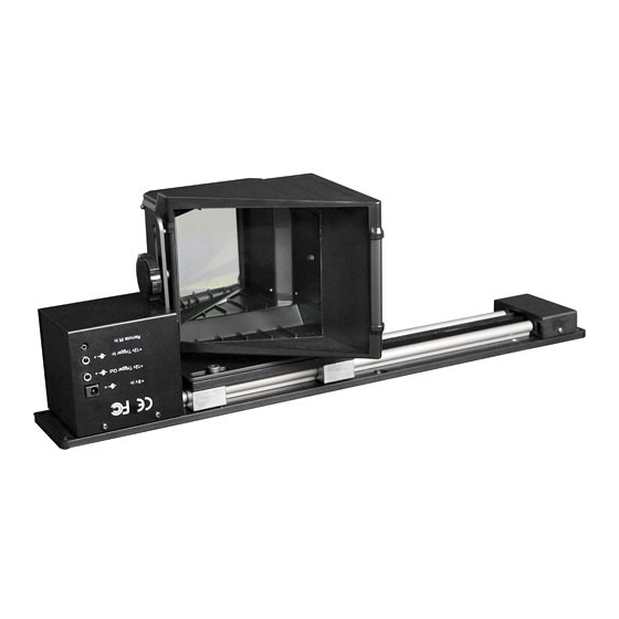
User’s Manual BX-AL133 Getting to Know Your System Motorized Sled Status LED Infrared Remote Sensor Mounting Plate Rail Drive Belt Reversable Logo Plate Rail Bearing (X4) Lens Adaptor Plate Pulley Housing Cover Motor Housing Cover Remote IR Sensor Rear Panel View... -
Page 5: Plan Your Installation
For more information, please visit our website at: http://www.OptomaUSA.com User’s Manual Remove Screws Remove Screws Replace Screws User’s Manual | BX-AL133 Rotate Logo Upright... - Page 6 There are score marks on the back of the mounting bar that correspond to the center of the BX-AL133 expansion lens. Before starting, the projector must be correctly focused with the zoom and iris set in their viewing positions. This will assure that the front of the lens is positioned correctly.
- Page 7 Remove the bracket mounting screws from the inside holes in the adaptor plate and use them to attach the lens bracket supplied with the Optoma BX-AL133 anamorphic lens system. If the lens is attached to the bracket, make sure to remove the lens prior to attaching to the lens adaptor plate.
- Page 8 User’s Manual BX-AL133 Setup 1. Power up the sled and set LENS IN position Slide the lens into the middle of the sled before powering up. Plug the power adaptor into an AC outlet, then into the back of the unit as illustrated. Using the remote, press the “lens in” button. The lens sled will slowly position itself into the factory default LENS IN position.
- Page 9 3. Attaching the lens to the bracket Attach the Optoma BX-AL133 anamorphic lens to the bracket using the plastic knobs supplied with the lens. Adjust the anamorphic lens vertically for correct alignment. When the image is correct, tighten the knobs against the bracket. Using the remote, test run LENS IN and LENS OUT commands.
- Page 10 PANEL OFF – Turns the logo backlight off. FAST PANEL ON – Turns the logo backlight on. SLOW – Sets the acceleration/deceleration and maximum speed for slow (low inertia) traversal. FAST – Sets the acceleration/deceleration and maximum speed for rapid traversal. User’s Manual BX-AL133 User’s Manual |...
- Page 11 For more information, please visit our website at: http://www.OptomaUSA.com User’s Manual Rear Panel View +9V DC In +12V Trigger Out +12V Trigger In Remote IR Sensor In BX-AL133 To screen masking system From projector or scaler User’s Manual |...
-
Page 12: Cleaning And Maintenance
Cleaning and Maintenance The Optoma BX-AL133 anamorphic lens system is maintenance-free. It will deliver many years of trouble-free service as delivered from the factory. To clean: Lightly blow off any surface debris from the lens. If needed, clean the lens using standard cleaning supplies while the projector is on (be careful not to look directly into the light beam of the projector. -
Page 13: Specifications
2, One Fixed, Another Remotely Attached (Optional) 50 ft from IR Sensor 38 kHz 2 AAA (for Remote) FCC, CE (BX-AL133 Motor Drive Unit) UL Class II (Power Supply Only) Greater than 250,000 rail traversals 5 lbs See accompanying drawings BX-AL133 User’s Manual |... - Page 14 (Motor Side) 2.5” 7.25” 10.842” 3.579” 3.402” For more information, please visit our website at: http://www.OptomaUSA.com 19.675” 4.511” 7.705” 13.738” 5.094” 4.97” 6.921” 5.973” 5.519” User’s Manual BX-AL133 Score Mark (Pulley Side) 3.0” 5.375” 8.333” 1.079” .25” 1.52” User’s Manual |...
-
Page 15: Warranty
Warranty Optoma Technology Inc. warrants this product to be free of defects in original workmanship and material for a period of twenty-four (24) months from the date of purchased. During this period, a defective unit may be repaired or replaced, at the discretion of Optoma Technology Inc., by returning it in its original packaging with a copy of your receipt. - Page 16 16:9 image orientation in the center of your 2.35:1 screen. For more information, please visit our website at: http://www.OptomaUSA.com User’s Manual Lens Plate Ceiling Side (Top) BX-AL133 Front Holes For: Projector and Ceiling Mount Hooks Lens Only Motorized Sled User’s Manual |...
- Page 17 Periodically check all fasteners and connection hardware to be sure they have not come loose. Improper installation may lead to an increased risk of your equipment becoming unstable and possibly causing injures. For more information, please visit our website at: http://www.OptomaUSA.com User’s Manual BX-AL133 User’s Manual |...
- Page 18 User’s Manual BX-AL133 Addendum: The Finished Product For more information, please visit our website at: User’s Manual | http://www.OptomaUSA.com...
- Page 19 715 Sycamore Drive Milpitas, CA 95035, USA Tel: 408-383-3700 .OptomaUSA.com Optoma Technology, Inc. 715 Sycamore Drive, Milpitas CA 95035 .Optoma.com. Specifications subject to change without notice. Copyright 2007 Optoma Technology, Inc. .Optoma.com...
Need help?
Do you have a question about the BX-AL133 and is the answer not in the manual?
Questions and answers