Advertisement
Quick Links
Installation and Assembly:
Optoma Universal Projector Mount By Peerless
Model: BM-5001U
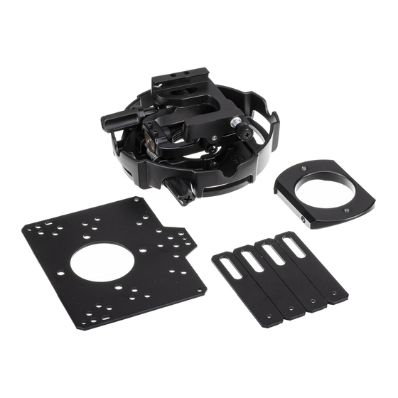
Parts List
Description
A main plate
B extension bracket
C precision gear projector mount
D 10-32 x 3/8" socket pin serrated washer head screw
E 10-32 x 1/4" socket pin with lock patch
F
4 mm security allen wrench
G 6.5 ID x 17.8 OD x 1.6 mm flat washer
H #14 x 2.5 hex phillips wood screw
alligator anchor
I
J
2 mm security allen wrench
K #4 flat washer
L
.219 ID x .5 OD x .125 spacer
M .219 ID x .5 OD x .25 spacer
N #8 flat washer
O M3 x 12 mm socket pin serrated washer head screw
P M4 x 16 mm socket pin serrated washer head screw
Q M4 x 8 mm socket pin serrated washer head screw
R M6 x 16 mm socket pin screw
AA connection block
D
E
I
M
NOTE: The following pages show the attachment points and hardware required to attach main plate
to projectors.
NOTE: Before installation review the directory on page 2 to find projector configuration.
3215 W. North Ave. • Melrose Park, IL 60160 • (800) 729-0307 or (708) 865-8870 • Fax: (708) 865-2941 • www.peerlessmounts.com
Max Load Capacity: 50 lb (22.6 kg)
F
J
O
N
Qty.
Part #
1
055-1939
4
055-1940
1
055-KPRGU-B-3
2
520-1151
1
520-1196
1
560-9646
2
540-1078
2
5S1-015-C03
2
590-0097
1
560-1097
8
540-1049
6
540-1032
4
540-9413
8
540-1001
4
510-1003
C
4
510-1087
4
510-1005
4
520-1132
1
580-1065
G
P
This product is intended for use with UL
Listed products and must be installed by a
qualified professional installer.
R
A
B
AA
L
K
Q
ISSUED: 04-20-09 SHEET #: 056-9019-7 09-07-10
H
R
Advertisement

Related Manuals for Optoma BM-5001U


Summary of Contents for Optoma BM-5001U
- Page 1 Installation and Assembly: Optoma Universal Projector Mount By Peerless This product is intended for use with UL Model: BM-5001U Listed products and must be installed by a Max Load Capacity: 50 lb (22.6 kg) qualified professional installer. Parts List Description Qty.
- Page 2 Locate Projector Model, Corresponding Page Projector Model Directory Projector Config. Page Screw Projector Config. Page Screw Projector Config. Page Screw Projector Config. Page Screw DS611 EP1691 HD200X TW775 DS316 EP7155 HD640 TW1692 DS317 ES520 HD700X TWR1693 DV11 ES522 HD710 TX532 DX606V ES526 HD803 TX536 DX607...
-
Page 3: Installation To Wood Joist Ceilings
Installation To Wood Joist Ceilings WARNING • Installer must verify that the supporting surface will safely support the combined load of the equipment and all attached hardware and components. • Tighten wood screws so that projector mount assembly is firmly attached, but do not overtighten. Overtightening can damage the screws, greatly reducing their holding power. - Page 4 Note: When attaching extension brackets (B) be sure to keep fasteners in the center of the slot. POSITION SCREW, SPACER AND WASHER IN CENTER OF SLOT CORRECT INCORRECT Note: Refer to to the Projector Mount Directory for projector mounting pattern and fasteners. CONFIGURATION A Attach plate (A) to projector using three Attach connection block (AA) to plate (A) using...
- Page 5 CONFIGURATION B Attach connection block (AA) to plate (A) using Attach plate (A) to projector using four two #10-32 x 3/8” serrated socket pin screws (D) M3 x 12 mm socket pin serrated washer head and .219 ID x .5 OD x .125 screws (O), #4 flat washers (K) and spacers (L).
- Page 6 CONFIGURATION D Attach plate (A) to projector using three Attach connection block (AA) to plate (A) using M4 x 16 mm socket pin serrated washer head two #10-32 x 3/8” serrated socket pin screws (D) screws (P), and spacer (M). and .219 ID x .5 OD x .125 spacers (L).
- Page 7 CONFIGURATION F Attach connection block (AA) to plate (A) using Attach two extension brackets (B) to plate two #10-32 x 3/8” serrated socket pin screws (D) (A) using two M4 x 8 mm serrated socket pin and .219 ID x .5 OD x .125 screws (Q).
- Page 8 CONFIGURATION H Attach connection block (AA) to plate (A) using Attach four extension brackets (B) to plate two #10-32 x 3/8” serrated socket pin screws (D) (A) using four M4 x 8 mm serrated socket pin and .219 ID x .5 OD x .125 screws (Q).
-
Page 9: Top View
CONFIGURATION J Attach connection block (AA) to plate (A) Attach one extension bracket (B) to plate (A) using two #10-32 x 3/8” serrated socket using one M4 x 8 mm serrated socket pin pin screws (D) and .219 ID x .5 OD x .125 screw (Q). - Page 10 CONFIGURATION K Attach connection block (AA) to plate (A) using Attach two extension brackets (B) to plate two #10-32 x 3/8” serrated socket pin screws (D) (A) using two M4 x 8 mm serrated socket pin and .219 ID x .5 OD x .125 screws (Q).
-
Page 11: Attaching Adapter Plate To Projector Mount
Attaching Adapter Plate to Projector Mount WARNING • Do not lift more weight than you can handle. Use additional man power or mechanical lifting equipment to safely handle placement of the screen. Slide connection block (AA) with precision gear projector mount (C) as shown. Tighten captive screw to secure precision gear projector mount (C).
Need help?
Do you have a question about the BM-5001U and is the answer not in the manual?
Questions and answers