
Related Manuals for GE VARIVENT S Series


Summary of Contents for GE VARIVENT S Series
- Page 1 Hygienic valves ® GEA VARIVENT control valve type S Operating instruction (Translation from the original language) 430BAL011074EN_5...
- Page 2 COPYRIGHT These Operating Instructions are the English translation of the original operating instructions in the sense of the EU Machinery Directive. This document is protected by copyright. All rights reserved. The document may not, in whole or in part, be copied, reproduced, translated or reduced to an electronic medium of machine-readable form without the express permission of GEA Tuchenhagen GmbH.
-
Page 3: Table Of Contents
TABLE OF CONTENTS General Information Information on the Document 1.1.1 Binding Character of These Operating Instructions 1.1.2 Notes on the Illustrations 1.1.3 Symbols and Highlighting Manufacturer address Contact EC Declaration of Conformity Safety Intended use 2.1.1 Requirements for operation 2.1.2 Pressure equipment directive 2.1.3 ATEX directive... - Page 4 9.1.1 Cleaning Process Examples 9.1.2 Cleaning effect Passivation Maintenance 10.1 Safety instructions 10.2 Inspections 10.2.1 Product contact seals 10.2.2 Pneumatic connections 10.2.3 Electrical connections 10.3 Maintenance intervals 10.4 Prior to disassembly 10.5 Disassembling the Valve 10.5.1 Disassembling Valve N 10.5.2 Disassembling Valves W + X 10.5.3 Disassembling the 3-Stage Seat / Double Stem Guide...
-
Page 5: General Information
General Information Information on the Document General Information Information on the Document The present Operating Instructions are part of the user information for the product. The Operating Instructions contain all the information you need to transport, install, commission, operate and carry out maintenance for the product. 1.1.1 Binding Character of These Operating Instructions These Operating Instructions contain the manufacturer's instructions to the... -
Page 6: Manufacturer Address
General Information Manufacturer address Warning! Warning: Serious Injuries Failure to observe the warning can result in serious damage to health. ► The arrow identifies a precautionary measure you have to take to avoid the hazard. Caution! Warning: Injuries Failure to observe the warning can result in minor or moderate damage to health. -
Page 7: Ec Declaration Of Conformity
General Information EC Declaration of Conformity EC Declaration of Conformity 430BAL011074EN_5 08.11.2021... - Page 8 General Information EC Declaration of Conformity 430BAL011074EN_5 08.11.2021...
- Page 9 General Information Fig.1 430BAL011074EN_5 08.11.2021...
-
Page 10: Safety
Safety Intended use Safety Intended use The control valve S is used to control flow rates and pressures in automated process plants. The medium should preferably flow in the opening direction of the valve disk to avoid pipe hammers when the valve is opened or closed. Hint! The manufacturer will not accept any liability for damage resulting from any use of the valve which is not in accordance with the... -
Page 11: Operator's Duty Of Care
Safety Operator’s Duty of Care The operational safety of the component can not be guaranteed under improper operating conditions. Therefore avoid improper operating conditions. The operation of the component is not permitted if: • Persons or objects are in the danger zone. •... -
Page 12: Subsequent Changes
Safety Subsequent changes Hint! Carry out regular checks. This way you can ensure that these measures are actually observed. Subsequent changes No technical modifications should ever be made to this component. Otherwise you will have to undergo a new conformity process in accordance with the EC Machinery Directive on your own. -
Page 13: Electrical Equipment
Safety Supplementary Regulations For environmental protection the following principles apply: • Substances harmful to the environment must not be discharged into the ground or the sewage system. • Always observe the pertinent regulations relating to waste avoidance, disposal and utilization. •... - Page 14 Safety Qualification of personnel The following minimum qualifications are required: • Training as a specialist for working independently on the component. • Adequate instruction to work on the component under the supervision and guidance of a trained specialist Each employee must meet the following requirements to work on the component: •...
-
Page 15: Safety Equipment
Safety Safety equipment Safety equipment 2.7.1 Signage Dangerous points on the valve are indicated by warning signs, prohibition signs and mandatory signs. The signs and notes on the valve must always be legible. Any illegible signs must be replaced immediately. Signs on the valve Sign Meaning... -
Page 16: Danger Zones
Safety Danger zones Residual dangers on the valve and measures Danger Cause Measure Danger of injury Danger presented by moving or The operator must exercise caution and prudence. sharp-edged parts For all work: • Wear suitable work clothing. • Never operate the machine if the cover panels are not correctly fitted. -
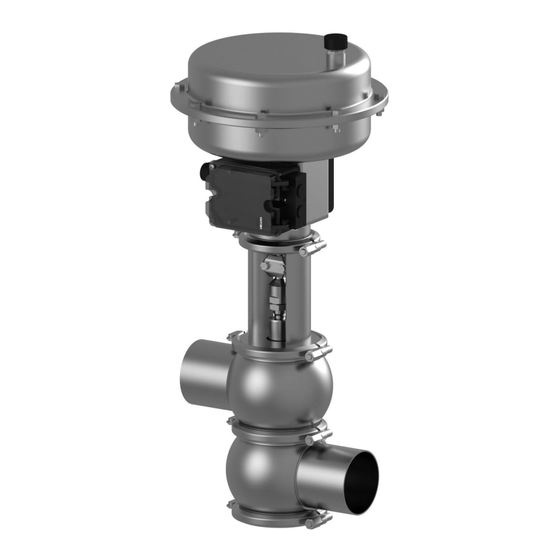
Page 17: Description
Description Design Description Design Fig.5 430BAL011074EN_5 08.11.2021... - Page 18 Description Design Design Designation Actuator Air connection Coupling clips Motor stool Adapter Valve disk Valve housing 430BAL011074EN_5 08.11.2021...
-
Page 19: Functional Description
Description Functional description Functional description 3.2.1 Spring-to-close actuator (Z) The valve is closed in the non-actuated position. In the standard version, the control valve is supplied with a spring-to-close actuator – spring closed in the non-actuated position –, i.e.: If the input signal at the positioner increases, the control valve opens. -
Page 20: Transport And Storage
Transport and storage Storage conditions Transport and storage Storage conditions The valves, valve inserts or spare parts should be stored in a dry place, free of vibrations and dust, and protected from light. To avoid damage, leave the components in their original packaging if possible. If, during transport or storage, the valve is going to be exposed to temperatures ≤... -
Page 21: Technical Data
Technical data Type plate Technical data Type plate The type plate clearly identifies the valve. Fig.6 The type plate provides the following key data: Key data of the valve Type Modulating Control Valve S Serial Serial number Material 1.4404 (AISI316L)/EPDM (FDA) Control air pressure bar/psi min. -
Page 22: Technical Data
Technical data Technical data Fig.7: Marking on motor stool - closed position Technical data Refer to the following tables for the key technical data of the valve: Technical data: Valve Designation Description DN 25 to DN 150 Size 1" to 6" OD 2"... -
Page 23: Seat Leakage According To Din En 60534-4
Technical data Seat leakage according to DIN EN 60534-4 Technical data: Ambient temperatures Designation Description -15 to 80°C < 0°C: Ambient temperature use control air with a low dew point. Protect valve stems against freezing. Operating temperature Depending on the sealing material Technical data: Compressed air supply Designation Description... -
Page 24: Resistance Of Sealing Materials
Technical data Resistance of Sealing Materials Fig.8: Soft-sealing seat version (VARIVENT® Fig.9: Metallic seat version principle with V-ring) The soft-sealing seat version is subject to leakage class VI. This results in the following exemplary permissible seat leakages for 5 barg (test medium air). KVS (m 3 /h) Permissible leakage 0.23... -
Page 25: Pipe Ends - General Table Of Measurements
Technical data Pipe ends - General table of measurements Sealing resistance table Gasket material Medium Temperature (general operating temperature) EPDM HNBR -40...+135°C -10...+200 °C -25...+140 °C (-40...275°F) (+14...+392°F) (-13...+284°F) Caustics up to up to 80 °C (176°F) Caustics up to up to 40 °C (104°F) Caustics up to... - Page 26 Technical data Pipe ends - General table of measurements Dimensions for Pipes in DN Outside Outside Wall Inside Metric DN diameter acc. diameter thickness diameter to DIN 11850 Dimensions for Pipes in Inch OD Outside Outside Wall Inside Inch OD diameter acc.
-
Page 27: Tools
Technical data Tools Tools List of tools Tools Material no. Hex. screwdriver SW 6 (for hex. socket-head 408-124 screws) Screwdriver, crosstip size 2 406-125 Screwdriver, blade width 3.5 406-103 Open end spanner a/f 6x7 408-030 Open end spanner a/f 8x10 408-032 Open end spanner a/f 13x17 408-036... -
Page 28: Auxiliary Equipment
Technical data Auxiliary equipment Auxiliary equipment Fig.10 Auxiliary equipment Air connection X Designation Material no. Metric version Reducing nipple G1/8-G3/8'' 933-048 Screw-in plug connection G1/8"-6/4 933-176 Inch version Reducing nipple G1/8-G3/8'' 933-048 Screw-in plug connection G1/8"-6.35 933-173 Lubricants Lubricants Designation Material no. -
Page 29: Weights
Technical data Weights Weights Weights Size Weight* [kg] DN 25, 1" approx. 14.0 DN 40, 1.5" approx. 15.0 DN 50, 2" approx. 15.5 DN 65, 2.5" approx. 21.0 DN 80, 3" approx. 21.0 DN 100, 4" approx. 24.0 DN 125 approx. -
Page 30: Assembly And Installation
Assembly and installation Safety instructions Assembly and installation Safety instructions Hazardous situations during installation can be avoided by safety-conscious and proactive behaviour of the personnel. For installation, the following principles apply: • Only qualified personnel are allowed to set-up, install and commission the component. -
Page 31: Valve With Welded Ends
Assembly and installation Valve with Welded Ends Fit valves with detachable pipe connection elements – using suitable connection fittings – directly into the pipe system. ® Valve is installed. Valve with Welded Ends This section describes the welding procedure for the valve housing. Warning! Spring tension in the valve Danger of injury when opening the clamp connections on the actuator or on... -
Page 32: Pneumatic Connections
Assembly and installation Pneumatic connections Hint! Welding method: we recommend using the TIG welding method. Housing O-rings: When assembling the valve always replace the housing O-rings to ensure that the valve is tight. Pneumatic connections Prerequisite: • The control air pressure may be max. 6 or 7 bar. Please observe the max. supply air pressure specified for the positioner used. - Page 33 Assembly and installation Pass the cable through the cable gland (1) and connect it according to the wiring diagram (in the protection cap of the positioner). Observe the operating instructions for the positioner. Fig.12 Tighten the strain-relief device on the cable gland (1). ®...
-
Page 34: Start-Up
Start-up Safety instructions Start-up Safety instructions Initial commissioning For initial commissioning, the following principles apply: • Take protective measures against dangerous contact voltages in accordance with pertinent regulations. • The valve must be completely assembled and correctly adjusted. All screw connections must be securely tightened. -
Page 35: Operation And Control
Operation and control Safety instructions Operation and control Safety instructions Dangerous situations during operation can be avoided by safety-conscious and proactive behaviour of the personnel. For operation, the following principles apply: • Monitor the component during operation. • Safety devices must not be changed, removed or taken out of service. Check all safety devices at regular intervals. -
Page 36: Cleaning
Cleaning Cleaning Cleaning Cleaning All parts in contact with product must be cleaned at regular intervals. Always observe the safety data sheets issued by the cleaning agent manufacturers. Only use cleaning agents which do not cause damage to the seals and the inner parts of the valve. -
Page 37: Passivation
Cleaning Passivation We recommend a flow velocity of at least 2 m/s. Passivation Before commissioning a plant, passivation is commonly carried out for long pipes and tanks. Valve blocks are usually excepted from this. Passivation is typically performed using nitric acid (HNO ) at approx. -
Page 38: Maintenance
Maintenance Safety instructions Maintenance 10.1 Safety instructions Maintenance and repair Before carrying out maintenance and repair work on the component's electrical equipment, perform the following steps in accordance with the "5 safety rules": • Isolate from the power supply • Take appropriate measures to prevent switch on •... -
Page 39: Inspections
Maintenance Inspections • Disconnect all power and utility lines. • Markings, e.g. on lines, must not be removed. • Do not climb on the component. Use suitable access aids and working platforms. • Mark the lines (if unmarked) prior to disassembly to ensure they are not confused when re-assembling. -
Page 40: Prior To Disassembly
Maintenance Prior to disassembly • switching frequency, • type and temperature of the product, • type and temperature of the cleaning solution, • ambient conditions. Maintenance Intervals Maintenance intervals Applications (guideline values) Media at temperatures of 60 °C to 130 °C approx. - Page 41 Maintenance Disassembling the Valve Fig.13 Prerequisite: • No positioner must be actuated electrically or manually. 430BAL011074EN_5 08.11.2021...
-
Page 42: Disassembling Valves W + X
Maintenance Disassembling the Valve Warning! Spring tension in the valve (spring-to-close action) Danger of injury when detaching the clamp connections (43, 46) as the released spring pretension will suddenly lift the actuator. ► Therefore, release the spring tension before detaching the clamp connections by pressurizing the actuator with compressed air at max. - Page 43 Maintenance Disassembling the Valve Disassembly - Valve W Fig.14 Prerequisite: • No positioner must be actuated electrically or manually. 430BAL011074EN_5 08.11.2021...
- Page 44 Maintenance Disassembling the Valve Warning! Spring tension in the valve (spring-to-close action) Danger of injury when detaching the clamp connections (43, 46) as the released spring pretension will suddenly lift the actuator. ► Therefore, release the spring tension before detaching the clamp connections by pressurizing the actuator with compressed air at max.
- Page 45 Maintenance Disassembling the Valve Disassembly - Valve X Fig.15 Prerequisite: • No positioner must be actuated electrically or manually. 430BAL011074EN_5 08.11.2021...
- Page 46 Maintenance Disassembling the Valve Warning! Spring tension in the valve (spring-to-close action) Danger of injury when detaching the clamp connections (43, 46) as the released spring pretension will suddenly lift the actuator. ► Therefore, release the spring tension before detaching the clamp connections by pressurizing the actuator with compressed air at max.
-
Page 47: Disassembling The 3-Stage Seat / Double Stem Guide
Maintenance Disassembling the Valve Carefully pull the valve insert complete with actuator (A) and motor stool (9) upwards to remove it from the valve housing (401.1). ! The bearing disk (4) and the sealing disk (3) must not hit against the stem of the valve disk when the valve insert is withdrawn. - Page 48 Maintenance Disassembling the Valve Fig.16 * only valid for DN 25 and 1" OD Prerequisite: • No positioner must be actuated electrically or manually. 430BAL011074EN_5 08.11.2021...
-
Page 49: Dismantling The Actuator Back Plate
Maintenance Disassembling the Valve Warning! Spring tension in the valve (spring-to-close action) Danger of injury when detaching the clamp connections (43, 46) as the released spring pretension will suddenly lift the actuator. ► Therefore, release the spring tension before detaching the clamp connections by pressurizing the actuator with compressed air at max. - Page 50 Maintenance Disassembling the Valve Warning! Spring tension in the valve Danger of injury when opening the back plate as the released spring pretension will suddenly lift the back plate. ► Therefore never slacken all the screws of the back plate at the same time.
-
Page 51: Maintenance
Maintenance Maintenance Fig.17 Slacken the hex nuts of the long screws slowly and at evenly distributed points along the circumference so that the two housing parts drift apart and the spring pretension is reduced. ® Done 10.6 Maintenance 10.6.1 Cleaning the Valve 430BAL011074EN_5 08.11.2021... -
Page 52: Replacing Seals
Maintenance Maintenance Notice Sealing grooves and contact surfaces are precision areas. Damage to the valve can result in a malfunction. ► Observe the safety information sheets issued by the detergent manufacturers! ► Only use detergents which are not aggressive towards the materials of the valve, and which are non-abrasive. -
Page 53: Lubricating Seals And Threads
Maintenance Maintenance Fig.19 Before fitting, wet the V-ring on the side not in contact with product (rear side). Pay attention that water does not drip into the V-ring groove on the valve disk. Put in the V-ring. Make sure the installation position of the V-ring is correct (see illustration). -
Page 54: Installation
Maintenance Installation Caution! Damage to seals and threads Damage to seals and threads can result in a malfunction. ► Ensure that an adequate film of lubricant is applied. No grease residues must be visible once the valve has been assembled completely. ►... - Page 55 Maintenance Installation ! Pay attention that the seat rings are positioned correctly: Soft sealing valve disks: inclined seating surface must face the valve disk (A). Metallically sealing valve disks: pointed edge must face the valve disk (B). Fig.23 Fig.22 Restore the tension of the actuator spring. Check the valve function by actuation using compressed air or signal current.
-
Page 56: Checking The Function
Maintenance Checking the function 10.8 Checking the function Setting the valve stroke Fig.24 Prerequisite: • Valve has been completely fitted into the housing. 10.8.1 Setting the valve stroke 430BAL011074EN_5 08.11.2021... -
Page 57: 10.8.1.1 Nc: Valve In Closed Position
Maintenance Checking the function Fig.25 • Valve has been completely fitted into the housing. 10.8.1.1 NC: Valve in closed position Carry out the following steps: Remove the coupling clips (6). 430BAL011074EN_5 08.11.2021... -
Page 58: 10.8.1.2 No: Valve In Open Position
Maintenance Checking the function Actuate the valve with compressed air (for data refer to type plate of the actuator): ® 2.7 bar/39 psi in this case Fig.26 1 stroke 2 air pressure Release the lock nut (76). Set the stroke between the adapter (10) and the actuator stem (A.2), see type plate;... -
Page 59: Valve Stroke
Maintenance Fig.27 Remove the coupling clips (6). Release the lock nut (76). Remove the compressed air. Set the stroke between the adapter (10) and the actuator stem (A.2), see type plate; here: 15 mm. Continue to turn the adapter (10): ®... -
Page 60: Alarms
Alarms Malfunctions and remedies Alarms 11.1 Malfunctions and remedies In the event of malfunctions immediately deactivate the valve and secure it against inadvertent reactivation. Malfunctions may only be remedied by qualified staff, who must observe the safety instructions. Malfunction Cause Remedy Check the system Fault in the control system... -
Page 61: Decommissioning
Decommissioning Safety instructions Decommissioning 12.1 Safety instructions For shutting down, the following principles apply: • Switch off the compressed air. • Switch off the component with the main switch. • Padlock the main switch (if fitted) in the off position to prevent it from being switched back on. -
Page 62: Spare Parts List - Varivent Control Valve Type S S_F/S_J
Spare parts list - VARIVENT control valve type S S_F/S_J Spare parts list - VARIVENT control valve type S S_F/S_J Fig.30: Soft sealing Fig.29: Metallic seal Fig.31: Housing combinations 430BAL011074EN_5 08.11.2021... - Page 63 Spare parts list - VARIVENT control valve type S S_F/S_J Spare parts list, item 1-5, metric sizes (DN 25 - DN 65) Item Designation Material DN 25 DN 40 DN 50 DN 65 Seal ring EPDM 924-084 924-084 924-084 924-085 924-082 924-082 924-082...
- Page 64 Spare parts list - VARIVENT control valve type S S_F/S_J Spare parts list V-ring, metric sizes (DN 25 - DN 65) Item Designation K VS value Material DN 25 DN 40 DN 50 DN 65 V-ring 0.16 0.25 932-064 EPDM 932-073 0.63 932-120...
- Page 65 Spare parts list - VARIVENT control valve type S S_F/S_J Spare parts list V-ring, metric sizes (DN 80 - DN 150) Item Designation K VS value Material DN 80 DN 100 DN 125 DN 150 V-ring 35.0 EPDM 932-021 932-033 FFKM 932-114 HNBR...
- Page 66 Spare parts list - VARIVENT control valve type S S_F/S_J Spare parts list, item 9, metric sizes (DN 25 - DN 65) Item Designation Material DN 25 DN 40 DN 50 DN 65 Lantern 1.4301 229-167.02 229-168.11 229-168.07 229-168.08 Spare parts list, item 10, metric sizes (DN 25 - DN 65) Item Designation K VS value...
- Page 67 Spare parts list - VARIVENT control valve type S S_F/S_J Spare parts list, item 10, metric sizes (DN 80 - DN 150) Item Designation K VS value Material DN 80 DN 100 DN 125 DN 150 Adapter 1.4301 L=40 229-322.01 0.16 1.4301 L=50 229-322.02...
- Page 68 Spare parts list - VARIVENT control valve type S S_F/S_J Spare parts list valve disk SFM, equal percentage, metallic seal, metric sizes (DN 80 - DN 150) Item K VS value Material DN 80 DN 100 DN 125 DN 150 1.4404 0.16 1.4404...
- Page 69 Spare parts list - VARIVENT control valve type S S_F/S_J Spare parts list valve disk SJM, linear, metallic seal, metric sizes (DN 25 - DN 65) Item K VS value Material DN 25 DN 40 DN 50 DN 65 1.4404 on request 0.16 1.4404...
- Page 70 Spare parts list - VARIVENT control valve type S S_F/S_J Spare parts list valve disk SFW, equal percentage, with V-ring seal, metric sizes (DN 25 - DN 65) Item K VS value Material DN 25 DN 40 DN 50 DN 65 1.4404 on request 0.16...
- Page 71 Spare parts list - VARIVENT control valve type S S_F/S_J Spare parts list valve disk SJW, linear with V-ring seal, metric sizes (DN 25 - DN 65) Item K VS value Material DN 25 DN 40 DN 50 DN 65 1.4404 221-762.86 221-762.51...
- Page 72 Spare parts list - VARIVENT control valve type S S_F/S_J Spare parts list valve disk SJW, linear with V-ring seal, metric sizes (DN 80 - DN 150) Item K VS value Material DN 80 DN 100 DN 125 DN 150 1.4404 0.16 1.4404...
- Page 73 Spare parts list - VARIVENT control valve type S S_F/S_J Spare parts list, items 35, 43, 46, 75, 76, 401 and 402, metric sizes (DN 25 - DN 65) Item Designation Material DN 25 DN 40 DN 50 DN 65 Hexagon nut 1.4301 910-142...
- Page 74 Spare parts list - VARIVENT control valve type S S_F/S_J Spare parts list housing connection S, metallic seal, metric sizes (DN 25 - DN 65) Item K VS value Material DN 25 DN 40 DN 50 DN 65 1.4404 221-407.103 0.16 1.4404 221-407.103...
- Page 75 Spare parts list - VARIVENT control valve type S S_F/S_J Spare parts list housing connection S for V-ring seal, metric sizes (DN 80 - DN 150) Item K VS value Material DN 80 DN 100 DN 125 DN 150 1.4404 221-407.105 1.4404 221-407.105...
- Page 76 Spare parts list - VARIVENT control valve type S S_F/S_J Spare parts list item 1-5, inch OD Item Designation Material 1" 1.5" 2" 2.5" 3" 4" 6" Seal ring EPDM 924-084 924-084 924-084 924-085 924-085 924-085 924-088 924-082 924-082 924-082 924-083 924-083 924-083...
- Page 77 Spare parts list - VARIVENT control valve type S S_F/S_J Spare parts list V-ring, (K VS 0.1- 160), inch OD Item Designation K VS value Mate- 1" OD 1.5" OD 2" OD 2.5" OD 3" OD 4" OD 6" OD rial 932-035 932-036...
- Page 78 Spare parts list - VARIVENT control valve type S S_F/S_J Spare parts list valve disk SFM, equal percentage, metallic seal, inch OD K VS value Material 1" OD 1.5" OD 2" OD 2.5" OD 3" OD 4" OD 6" OD Item 1.4404 on request...
- Page 79 Spare parts list - VARIVENT control valve type S S_F/S_J Spare parts list valve disk SFW, equal percentage, with V-ring seal, inch OD K VS value Material 1" OD 1.5" OD 2" OD 2.5" OD 3" OD 4" OD 6" OD Item 1.4404 221-762.84...
- Page 80 Spare parts list - VARIVENT control valve type S S_F/S_J Spare parts list items 35, 43, 46, 75, 76, 401 and 402, inch OD Item Designation Mate- 1" OD 1.5" OD 2" OD 2.5" OD 3" OD 4" OD 6" OD rial Blanking plate 1.4404...
- Page 81 Spare parts list - VARIVENT control valve type S S_F/S_J Spare parts list items 1-5, inch IPS Item Designation Material 2" IPS 3" IPS 4" IPS 6" IPS Seal ring EPDM 924-084 924-085 924-085 924-088 924-082 924-083 924-083 924-087 FFKM 924-340 924-341 924-341...
- Page 82 Spare parts list - VARIVENT control valve type S S_F/S_J Spare parts list, item 9, inch IPS Item Designation Material 2" IPS 3" IPS 4" IPS 6" IPS Lantern 1.4301 229-168.18 229-168.12 229-168.13 229-168.06 Spare parts list, item 10, inch OD Item Designation K VS value...
- Page 83 Spare parts list - VARIVENT control valve type S S_F/S_J Spare parts list valve disk SJM, linear, metallic seal, inch IPS Item K VS value Material 2" IPS 3" IPS 4" IPS 6" IPS 1.4404 0.63 1.4404 1.4404 1.4404 1.4404 1.4404 1.4404 1.4404...
- Page 84 Spare parts list - VARIVENT control valve type S S_F/S_J Spare parts list valve disk SFW, equal percentage, with V-ring seal, inch IPS Item K VS value Material 2" IPS 3" IPS 4" IPS 6" IPS 1.4404 0.16 1.4404 0.25 1.4404 1.4404 0.63...
- Page 85 Spare parts list - VARIVENT control valve type S S_F/S_J Spare parts list valve disk SJW, linear with V-ring seal, inch IPS Item K VS value Material 2" IPS 3" IPS 4" IPS 6" IPS 1.4404 0.16 1.4404 0.25 1.4404 1.4404 0.63 1.4404...
- Page 86 Spare parts list - VARIVENT control valve type S S_F/S_J Spare parts list items 35, 43, 46, 75, 76, 401 and 402, inch IPS Item Designation Material 2" IPS 3" IPS 4" IPS 6" IPS Blanking plate 1.4404 221-144.02 221-144.03 221-144.04 221-144.05 Clamp join KL...
-
Page 87: Spare Parts List - Varivent Control Valve Type S, Divert Valve W/X
Spare parts list - VARIVENT control valve type S, divert valve W/X Spare parts list - VARIVENT control valve type S, divert valve W/X Fig.33: Type X (SXW) Fig.32: Type W (SWW) Fig.34: Housing combinations 430BAL011074EN_5 08.11.2021... - Page 88 Spare parts list - VARIVENT control valve type S, divert valve W/X Spare parts list items 1-9, metric sizes Item Designation Material DN 25 DN 40 DN 50 DN 65 DN 80 DN 100 Seal ring EPDM 924-084 924-084 924-084 924-085 924-085 924-085...
- Page 89 Spare parts list - VARIVENT control valve type S, divert valve W/X Spare parts list item 15, valve X - valve disk X1, linear, standard, metric sizes Item Designation value Material DN 25 DN 40 DN 50 DN 65 DN 80 DN 100 1.4404 221-762.27...
- Page 90 Spare parts list - VARIVENT control valve type S, divert valve W/X Spare parts list item 1-9, inch OD Item Designation Material 1" OD 1.5" OD 2" OD 2.5" OD 3" OD 4" OD Seal ring EPDM 924-084 924-084 924-084 924-085 924-085 924-085...
- Page 91 Spare parts list - VARIVENT control valve type S, divert valve W/X Spare parts list item 15, valve X - valve disk X1, linear, standard, inch OD Item Designation value Material 1" OD 1.5" OD 2" OD 2.5" OD 3" OD 4"...
-
Page 92: Spare Parts List - Varivent Control Valve Type S 3-Stage Seat K
Spare parts list - VARIVENT control valve type S 3-stage seat K Spare parts list - VARIVENT control valve type S 3-stage seat K Fig.35: X = only valid for DN 25 and 1" OD Fig.36: Housing combinations 430BAL011074EN_5 08.11.2021... - Page 93 Spare parts list - VARIVENT control valve type S 3-stage seat K Metric sizes DN 25 DN 40 DN 50 DN 65 DN 80 DN 100 Inch OD 1" OD 1.5" OD 2" OD 2.5" OD 3" OD 4" OD Spare parts list items 1-5, metric sizes Item Designation...
- Page 94 Spare parts list - VARIVENT control valve type S 3-stage seat K Spare parts list item 15, 3-stage seat, linear, standard, metric sizes Item Designatio Material DN 25 DN 40 DN 50 DN 65 DN 80 DN 100 value 34.6 1.4404 221-762.47 3x K...
- Page 95 Spare parts list - VARIVENT control valve type S 3-stage seat K Spare parts list item 1-5, inch OD Item Designation Material 1" OD 1.5" OD 2" OD 2.5" OD 3" OD 4" OD Sealing ring EPDM 924-084 924-084 924-084 924-085 924-085 924-085...
- Page 96 Spare parts list - VARIVENT control valve type S 3-stage seat K Spare parts list item 28, valve X, inch OD Item Designation Material 1" OD 1.5" OD 2" OD 2.5" OD 3" OD 4" OD O-ring (11 x 3) EPDM 930-311 930-335...
-
Page 97: Spare Parts List - Sterile Lock Hsp
Spare parts list – sterile lock HSP Spare parts list – sterile lock HSP Fig.37: X= sterile lock HSP, top; Y= sterile lock HSP, bottom; (Z)= only for bottom sterile lock 430BAL011074EN_5 08.11.2021... - Page 98 Spare parts list – sterile lock HSP Attention! Primary pressure at "A" max. 1 bar at free outlet Item Designation Material DN 25 DN 40 DN 40 1" OD 1.5" OD 1.5" OD 1.5" OD DN 50/40 Y-valve Y-valve with 2"...
- Page 99 Spare parts list – sterile lock HSP Attention! Primary pressure at "A" max. 1 bar at free outlet Item Designation Material DN 50/40 DN 80/65 DN 100 DN 125 6" IPS 1.5" / 2" OD 2.5" / 3" OD 4" OD 2"...
-
Page 100: Appendix
Appendix Lists Appendix 17.1 Lists 17.1.1 Abbreviations and terms Abbreviation Explanation British Standard Unit of measurement of pressure [bar] All pressure data expressed in [bar/psi] is assumed to be gauge pressure [barg/psig] unless explicitly specified otherwise. approx. approximately °C Unit of measurement of temperature [degree Celsius] Unit of measurement of volume [cubic decimetre] Standard volume (standard litre) DIN nominal width... - Page 101 Appendix Abbreviation Explanation Metric Unit of measurement of work [newton metre] Specification of torque 1 Nm = 0.737 lbft Pound-Force (lb) + Feet (ft) Polyamide PE-LD Low-density polyethylene Polytetrafluoroethylene America measurement for pressure [Pound-forse per square inch] All pressure data expressed in [bar/psi] is assumed to be gauge pressure [barg/psig] unless explicitly specified otherwise.
Need help?
Do you have a question about the VARIVENT S Series and is the answer not in the manual?
Questions and answers