
Related Manuals for CLA-VAL XP2F


Summary of Contents for CLA-VAL XP2F
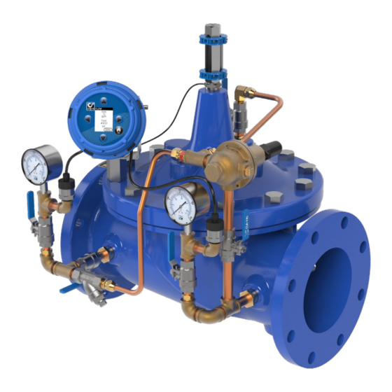
- Page 1 Model XP2F Metering Package Installation / Operation / Maintenance Written for Version 1.0...
-
Page 2: Table Of Contents
A.3 2x X141-PTs and X117D ............................... 32 A.4 DP Transmitter and X117D ..............................33 Appendix B: Full Data Acquisition Setup ............................34 B.1 Full Retransmission Wiring, 2x X141-PTs and X117H ......................34 B.2 Full Retransmission Device Settings ............................. 35 N-XP2F IOM V1.0-4.5 Page 2 of 35... -
Page 3: Introduction
1 Introduction The XP2F is a low cost, robust, state of the art package that can accurately meter the flow through a Cla- Val valve. To meter the flow, the XP2F assimilates data from valve mounted pressure transmitters and a position transmitter. -
Page 4: X117H Valve Position Transmitter
Installation, Operation, and Maintenance Manual 2 X117H Valve Position Transmitter The Cla-Val Model X117H Valve Position Transmitter is an accurate monitor of the valve position. Through an industry standard 4-20mA, the X117H delivers accuracy within 100 micrometers. This position transmitter easily provides the accuracy required for computer-guided control valve systems (SCADA). -
Page 5: X141-Pt Pressure Transmitters
Installation, Operation, and Maintenance Manual 3 X141-PT Pressure Transmitters The Cla-Val Model X141-PT consists of a pressure transmitter installed with isolation valves mounted on the main valve inlet and/or outlet. The rugged design provides resistance to vibration, shock, wide temperature variations, RFI and other extreme environmental conditions. Performance and reliability are enhanced by the all-stainless steel welded measuring cell that eliminates the need for soft sealing materials that may deteriorate over time. -
Page 6: X35 Flow Calculation Module
XP2F metering package. The X35 Module is responsible for handling all the input and output signals in the XP2F package. The X35 has four 4- 20mA inputs and four 4-20mA outputs. The standard inputs include Valve Position, Upstream and Downstream Pressure Transmitters or a single DP Transmitter. -
Page 7: Installation
To mount the X35 flow calculation module directly on a valve, assemble the X35 on the included rotating support bracket along with the X56 valve cover standoff supports using the fasteners as depicted in the Figure 4.2. Figure 4.2 N-XP2F IOM V1.0-4.5 Page 7 of 35... -
Page 8: Flat Surface Mount
To mount the X35 calculation module on a flat surface as shown in Figure 4.3, assemble the calculation module on the included rotating support bracket using the fasteners depicted in Figure 4.4. Figure 4.3 Figure 4.4 N-XP2F IOM V1.0-4.5 Page 8 of 35... -
Page 9: Installing Wire Cable Glands
WARNING: DO NOT leave any holes/glands open. Blanks can be used to block an entire port or if a custom sized hole needs to be drilled. Figure 4.5 – 4 wire config (1x 2hole, 1x drilled blank), 3 wire config (1x 3hole), 3 wire config (1x 2hole), 6 wire (1x 2hole, 1x 3hole) N-XP2F IOM V1.0-4.5 Page 9 of 35... -
Page 10: Electrical Wiring
4.2 Electrical Wiring 4.2.1 Overview The XP2F integrates several components electrically, and this section is designated to explain how those electrical connections should be made. The X35 flow calculation model is the connection point for all other components in the package, so the wiring is explained in terms of the X35. - Page 11 Model XP2F Installation, Operation, and Maintenance Manual For a field powered 4-20mA signal, see the wiring diagram in Figure 4.7. Figure 4.7 N-XP2F IOM V1.0-4.5 Page 11 of 35...
-
Page 12: Analog Outputs
X35 power supply (6 – 24 VDC). To have an external device (e.g. SCADA/PLC) receive the 4-20mA signal from the X35, wire the device as shown in Figure 4.8. Figure 4.8 N-XP2F IOM V1.0-4.5 Page 12 of 35... -
Page 13: Standard Wiring Diagram
Installation, Operation, and Maintenance Manual 4.2.5 Standard Wiring Diagram The following wiring diagram shows how to wire the standard XP2F (2x X141-PTs and X117H). Please note, the XP2F package can be offered with multiple different components and can also be configured to use different I/O channels. -
Page 14: Screen Navigation
Model XP2F Installation, Operation, and Maintenance Manual 4.3 Screen Navigation 4.10 below provides a screen map which shows how to navigate to various screens on the X35. IGURE Figure 4.10 N-XP2F IOM V1.0-4.5 Page 14 of 35... -
Page 15: Setup
4.4.1 Initial Configuration After the XP2F components are installed and wired, provide power to the X35 calculation module. Configure the unit following the steps below. 1. Starting at the home screen, use the navigation arrows to highlight “Setup” as shown below and press OK. - Page 16 Flow Direction: Normal (indicates flow is not going in reverse through the valve) Figure 4.14 5. Return to the home screen by pressing and holding the OK button for 2 seconds. The XP2F package is now ready for operation. N-XP2F IOM V1.0-4.5...
-
Page 17: Dpm Setup
Description: Allows the user to configure units for flow, number of decimal points to display, and a low flow cutoff. Any flow registered that is less than the low cutoff value is forced to zero. Figure 4.16 N-XP2F IOM V1.0-4.5 Page 17 of 35... - Page 18 Description: Specifies if an upstream and downstream pressure transmitter is connected to the X35, or if differential pressure transmitter is connected to the X35. P1+P2 (upstream and downstream transmitters) DP (Differential pressure transmitter) Figure 4.18 N-XP2F IOM V1.0-4.5 Page 18 of 35...
- Page 19 X35 and another flow meter when the discrepancy varies as the valve opens more. Gain factor applied to calculated flow when valve is 5% open Gain factor applied to calculated flow when valve is 15% open Figure 4.20 N-XP2F IOM V1.0-4.5 Page 19 of 35...
-
Page 20: I/O Setup
Figure 4.25. Opens input setup screen in Figure 4.23 Opens straight to Retransmission setup screen in Figure 4.25 Figure 4.22 N-XP2F IOM V1.0-4.5 Page 20 of 35... - Page 21 7 psi, a targeted new value of 7 psi may be entered which will offset the measured value by 2 psi from now on. Turns the New value to channel offset adjust input on/off too. Value currently measured Figure 4.24 N-XP2F IOM V1.0-4.5 Page 21 of 35...
-
Page 22: Calibration
Type of signal sent to channel (4-20mA or 0-10V) Reports current Enter correct signal signal X35 is measured on measuring. multimeter/SCADA, then press “Set Lo”. Repeat for “Set High”. Figure 4.26 N-XP2F IOM V1.0-4.5 Page 22 of 35... -
Page 23: Display Options
How many minutes of idle time Light mode is before screen useful when turns off screen is in a dark room. Dark mode is useful when screen is in direct sunlight. Figure 4.28 N-XP2F IOM V1.0-4.5 Page 23 of 35... -
Page 24: Logging
SD Card Features section. DO NOT remove the SD card unless the X35 is powered down! Doing so may corrupt all the data on the SD card. Figure 4.30 N-XP2F IOM V1.0-4.5 Page 24 of 35... -
Page 25: Date/Time
4.4.7 Date/Time Description: Used to set current date and time. Date and time formats can also be changed. Figure 4.31 4.4.8 Language Description: Used to change the language displayed on the screen. Figure 4.32 N-XP2F IOM V1.0-4.5 Page 25 of 35... -
Page 26: Factory Reset
Model XP2F Installation, Operation, and Maintenance Manual 4.4.9 Factory Reset Description: Used to reset all settings back to the factory defaults. Figure 4.33 N-XP2F IOM V1.0-4.5 Page 26 of 35... -
Page 27: Sd Card Features
3. Either, carefully pick up the SD card, ensuring it does not fall under the black plastic cover, OR more easily, hold the SD card against the board with your finger and then flip the module over and remove your finger. SD card should be on top of finger. Figure 4.35 N-XP2F IOM V1.0-4.5 Page 27 of 35... -
Page 28: Access Logged Data
4. The copied zip files should be extracted to access the .csv log file. 5. After log files have been copied, insert the SD card back into the X35 and connect power. Exported Logs will be stored here as ZIP files. Figure 4.36 N-XP2F IOM V1.0-4.5 Page 28 of 35... -
Page 29: Firmware Update
In order to update the X35 firmware, you will need access to a MicroSD card reader. The newest firmware files are available from the Cla-Val website or your Cla-Val representative. 1. Insert the SD card into your PC and locate the Root directory shown in Figure 4.37. -
Page 30: Appendix A: Wiring Diagram Examples
Model XP2F Installation, Operation, and Maintenance Manual Appendix A: Wiring Diagram Examples A.1 2x X141-PTs and X117H Figure A.1 N-XP2F IOM V1.0-4.5 Page 30 of 35... -
Page 31: Dp Transmitter And X117H
Model XP2F Installation, Operation, and Maintenance Manual A.2 DP Transmitter and X117H Figure A.2 N-XP2F IOM V1.0-4.5 Page 31 of 35... -
Page 32: X141-Pts And X117D
Model XP2F Installation, Operation, and Maintenance Manual A.3 2x X141-PTs and X117D Figure A.3 N-XP2F IOM V1.0-4.5 Page 32 of 35... -
Page 33: Dp Transmitter And X117D
Model XP2F Installation, Operation, and Maintenance Manual A.4 DP Transmitter and X117D Figure A.4 N-XP2F IOM V1.0-4.5 Page 33 of 35... -
Page 34: Appendix B: Full Data Acquisition Setup
Model XP2F Installation, Operation, and Maintenance Manual Appendix B: Full Data Acquisition Setup B.1 Full Retransmission Wiring, 2x X141-PTs and X117H Figure B.1 N-XP2F IOM V1.0-4.5 Page 34 of 35... -
Page 35: Full Retransmission Device Settings
B.2 Full Retransmission Device Settings Start from I/O Setup in Figure 4.22. “Retransmit to:” should be entered as follows. Min and Max will need to be changed based on application, sensors used, and desired output. Figure B.2 N-XP2F IOM V1.0-4.5 Page 35 of 35...
Need help?
Do you have a question about the XP2F and is the answer not in the manual?
Questions and answers