
Related Manuals for CLA-VAL XP2F


Summary of Contents for CLA-VAL XP2F
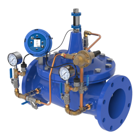
- Page 1 Model XP2F Metering Package Installation / Operation / Maintenance Written for Version 1.0...
-
Page 2: Table Of Contents
I/O Setup ............................. 18 Calibration ........................... 20 5.3.1 Inputs ..........................20 5.3.2 Outputs ..........................20 Display Options ........................... 21 Logging ............................21 5.5.1 Configure Logging ....................... 21 5.5.2 Export Log Files ........................22 N-XP2F IOM V1.0-3.0.docx Page 2 of 26... - Page 3 Language ............................. 22 Factory Reset ..........................23 Appendix A: Wiring Diagram Examples ...................... 24 A.1 2x X141-PTs and X117D ........................24 A.2 DP Transmitter and X117H ....................... 25 A.3 DP Transmitter and X117D ....................... 26 N-XP2F IOM V1.0-3.0.docx Page 3 of 26...
-
Page 4: Installation, Operation, And Maintenance Manual
1 Introduction The XP2F is a low cost, robust, state of the art package that can accurately meter the flow through a Cla- Val valve. To meter the flow, the XP2F assimilates data from valve mounted pressure transmitters and a position transmitter. -
Page 5: Quick Start
2 Quick Start The XP2F can be installed and configured in a matter of minutes. This section is intended to show a user how to quickly startup an XP2F package and skips some of the advanced configuration options. For more details on advanced configuration, see the subsequent sections. - Page 6 Model XP2F Installation, Operation, and Maintenance Manual Figure 2.2 Figure 2.3 N-XP2F IOM V1.0-3.0.docx Page 6 of 26...
-
Page 7: Installing The Position Transmitter
2.4 showing how the components of a standard xP2F package are IGURE wired together. Please note, the xP2F package can be offered with multiple different components and can also be configured to use different I/O channels. The diagram depicts what is standard. For more detailed wiring instructions, see subsequent sections. -
Page 8: Configuration
Model XP2F Installation, Operation, and Maintenance Manual 2.3 Configuration After the XP2F components are installed and wired, provide power to the X35 calculation module. 2.3.1 Calibrate the X117H Position Transmitter Please see the position transmitter manual for calibration instructions. 2.3.2 Configuring the X35 Calculation Module Configure the unit following the steps below. - Page 9 Flow Direction: Normal (indicates flow is not going in reverse through the valve) Figure 2.8 5. Return to the home screen by pressing and holding the OK button for 2 seconds. The XP2F package is now ready for operation. N-XP2F IOM V1.0-3.0.docx...
-
Page 10: Electrical Wiring
3 Electrical Wiring 3.1 Overview The XP2F integrates several components electrically, and this section is designated for explaining how those electrical connections should be made. The X35 calculation model is the connection point for all other components in the package, so the wiring is explained in terms of the X35. - Page 11 Model XP2F Installation, Operation, and Maintenance Manual To have the X35 provide loop power to the sensor, see the wiring diagram in F 3.2. IGURE Figure 3.2 N-XP2F IOM V1.0-3.0.docx Page 11 of 26...
-
Page 12: Analog Outputs
X35 power supply (6 – 24 VDC). To have an external device (e.g. SCADA/PLC) receive the 4-20mA signal from the X35, wire the device as shown in F 3.3. IGURE Figure 3.3 N-XP2F IOM V1.0-3.0.docx Page 12 of 26... -
Page 13: Standard Wiring Diagram
Model XP2F Installation, Operation, and Maintenance Manual 3.5 Standard Wiring Diagram The following wiring diagram shows how to wire the standard xP2F (2x X141-PTs and X117H) Figure 3.4 N-XP2F IOM V1.0-3.0.docx Page 13 of 26... -
Page 14: Screen Navigation
4.1 below provides a screen map which shows how to navigate to various screens on the X35. IGURE Figure 4.1 5 Setup The following sub sections define the show the settings on each screen and provide detailed descriptions when necessary. N-XP2F IOM V1.0-3.0.docx Page 14 of 26... -
Page 15: Dpm Setup
Description: Allows the user to configure units for flow, number of decimal points to display, and a low flow cutoff. Any flow registered that is less than the low cutoff value is forced to zero. Figure 5.2 N-XP2F IOM V1.0-3.0.docx Page 15 of 26... -
Page 16: Total
Description: Specifies if an upstream and downstream pressure transmitter is connected to the X35, or if differential pressure transmitter is connected to the X35. P1+P2 (upstream and downstream transmitters) DP (Differential pressure transmitter) Figure 5.4 N-XP2F IOM V1.0-3.0.docx Page 16 of 26... -
Page 17: Dpm Curve Adjust
X35 and another flow meter when the discrepancy varies as the valve opens more. Gain factor applied to calculated flow when valve is 2% open Gain factor applied to calculated flow when valve is 4% open Figure 5.6 N-XP2F IOM V1.0-3.0.docx Page 17 of 26... -
Page 18: I/O Setup
(Inlet Pressure, Outlet Pressure, Position, or Spare), then the input setup screen is display. If the flow output channel is selected, then the output setup screen is displayed. Opens input setup screen in IGURE Opens output setup screen in F 5.11 IGURE Figure 5.8 N-XP2F IOM V1.0-3.0.docx Page 18 of 26... - Page 19 7 psi, a targeted new value of 7 psi may be entered which will offset the measured value by 2 psi from now on. Turns the New value to adjust input channel offset on/off too. Value currently measured Figure 5.10 N-XP2F IOM V1.0-3.0.docx Page 19 of 26...
-
Page 20: Calibration
Figure 5.12 5.3.2 Outputs Description: Used when the milliamps/volts sent from an output channel on the X35 differ from the value measured on a multimeter or PLC/SCADA system. Allows the discrepancy to be eliminated. N-XP2F IOM V1.0-3.0.docx Page 20 of 26... -
Page 21: Display Options
12:00 AM, 12:05 AM, 12:10AM, … If configured to log every 5 min with offset from midnight at 1 min, log entries will be at 12:01 AM, 12:06 AM, 12:11 AM, … Figure 5.14 N-XP2F IOM V1.0-3.0.docx Page 21 of 26... -
Page 22: Export Log Files
Please note, do not remove the SD card unless the X35 is powered down. Doing so may corrupt all the data on the SD card. Figure 5.15 5.6 Language Description: Used to change the language displayed on the screen. Figure 5.16 N-XP2F IOM V1.0-3.0.docx Page 22 of 26... -
Page 23: Factory Reset
Model XP2F Installation, Operation, and Maintenance Manual 5.7 Factory Reset Description: Used to reset all settings back to the factory defaults. Figure 5.17 N-XP2F IOM V1.0-3.0.docx Page 23 of 26... -
Page 24: Appendix A: Wiring Diagram Examples
Model XP2F Installation, Operation, and Maintenance Manual Appendix A: Wiring Diagram Examples A.1 2x X141-PTs and X117D Figure 5.18 N-XP2F IOM V1.0-3.0.docx Page 24 of 26... -
Page 25: Dp Transmitter And X117H
Model XP2F Installation, Operation, and Maintenance Manual A.2 DP Transmitter and X117H Figure 5.19 N-XP2F IOM V1.0-3.0.docx Page 25 of 26... -
Page 26: Dp Transmitter And X117D
Model XP2F Installation, Operation, and Maintenance Manual A.3 DP Transmitter and X117D Figure 5.20 N-XP2F IOM V1.0-3.0.docx Page 26 of 26...
Need help?
Do you have a question about the XP2F and is the answer not in the manual?
Questions and answers