Sign In
Upload
Manuals
Brands
IAI Manuals
Controller
R-unit RSEL
IAI R-unit RSEL Manuals
Manuals and User Guides for IAI R-unit RSEL. We have
1
IAI R-unit RSEL manual available for free PDF download: Instruction Manual
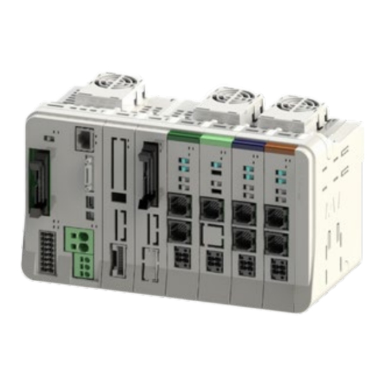
IAI R-unit RSEL Instruction Manual (844 pages)
Brand:
IAI
| Category:
Controller
| Size: 27 MB
Table of Contents
Table of Contents
37
Overview (about RSEL System)
38
Features
39
Specifications
42
General Specifications
42
Environmental Conditions
43
Supper Source Specifications
43
Specifications at Control Part
44
Usage Temperature Range
45
General Specifications
45
Installation
46
Installation Conditions
46
Installation and Mounting
47
Noise Countermeasures and Mounting Method
48
System Configuration
53
System Configuration Diagram
53
Configuration Unit
54
Model Code
57
Unit List
61
Set Model Code for 6-Axis Cartesian Robot
62
Teaching Tool (Option)
63
Power Supply Capacity
64
Power Supply Capacity
66
Unit Connection Restrictions
69
In-Rush Current
74
Generated Heat
76
Rush Current Sequence
77
Drive-Ssource Cutoff
78
Drive-Source Cutoff Circuit Specifications
78
Drive-Source Cutoff Circuit Wiring Example
79
Category 3 or Category 4 Configuration Example
81
SEL Unit, Terminal Unit
85
Overview
85
Model Code
86
Component
88
Part Names/Functions
89
External Dimensions
113
Driver Unit, Fun Unit
115
Overview
115
Model Code
116
Components
118
Part Names/Functions
119
External Dimensions
130
Power Supply Unit, for 200V Terminal Unit
132
Overview
132
Model Code
134
Components
137
Part Names/Functions
138
External Dimensions
145
Driver Unit, Fan Unit for 200V Driver
147
Overview
147
Model Code
149
Part Names/Functions
153
External Dimensions
160
Driver Stop Circuit
162
SCON Extension Unit, PIO/SIO/SCON Extension Unit
167
PIO Unit
167
Overview
167
Model Code
170
Components
172
Part Names/Functions
175
PIO Specifications
179
SIO Specifications
184
External Dimensions
185
EC Connection Unit
186
Overview
186
Model Code
187
Components
189
Part Names/Functions
190
External Dimensions
197
Simple Absolute Unit
198
Overview
198
Model Code
200
Components
202
General Specifications
203
Part Names/Functions
205
External Dimensions
207
Precautions
208
Unit Connection Restrictions
209
Motor Power / Control Power Capacity Restrictions
209
Unit Arrangement Restrictions
209
Unit Connection / Installation
214
Unit Connection
214
Fan Installation
215
Unit Mounting
216
Wiring Diagram
217
Example Connection of Devices
217
Circuit Diagram (Example)
218
Single-Phase Type Power Supply Circuit
218
3-Phase Type Power Supply Circuit
219
Wiring Method
220
Power Supply Wiring to RSEL System
220
Checking Actuator Model Numbers
224
RSEL Connection Cable List
225
Actuator Wiring (Connecting Motor/Encoder Cable)
228
Wiring between EC Connection Unit and ELECYLINDER
230
Simple Absolute Unit Wiring
238
Field Network Wiring
240
Regenerative Resistor (Option)
245
Regenerative Resistor Unit Specifications
245
Wiring for Regenerative Resistor Unit
246
Brake Box (Option)
248
Specification for Brake Box
248
Wiring for Brake Box
252
Connection the Teaching Connector
257
Connection the USB Connector
261
Connection the Ethernet Connector
262
Startup Procedure
265
Turning on the Controller Power and Cutoff
267
Power on
267
Power Cutoff
268
Axis Setting
269
RSEL Axis Setting
269
Starting Method
269
Simple Setting Method
270
Description of each Area
273
Special Mechanism Axis
275
Axis Group Setting
276
Receiving and Forwarding of
277
I/O Signals Necessary for Operation
277
I/O Port
278
Position Data (Position Table)
281
Programming
282
SEL Command Word List
282
Symbol Extension
282
Step Comment Number of Characters
282
Position Data Comment
282
Memory Map
284
Types of Operations
286
How to Operate
287
Auto Start Upon Power on
287
Starting a Program by Specifying Its Program Number
289
ELECYLINDER Operation
291
ELECYLINDER Control System
293
EC Connection Unit
294
Assignment and Operation System of EC Signals
301
Timing for Input and Output Signals
303
Maintenance Bit Output for Predictive Maintenance
304
Configuration Example
305
Caution
311
List of Related Parameters
312
Related Errors
315
Interface Specifications
321
I/O Slot
321
PIO/SIO/SCON Extension Unit, PIO Unit
331
Functional Specifications
332
List of Applicable Devices
332
Parallel I/O and Remote I/O
333
I/O Ports and Reading and Writing of Data
335
Example of Use of each Network, PIO, SIO
338
Parameter Configuration
371
Basic Setting
371
Other Settings
375
Examples of Parameter Settings at Delivery
376
Example of Use of each Network and Parameter
378
Caution
419
Network Setting Files
419
Profibus-Dp
420
Ethercat
421
Ethernet/Ip
421
Example of Connectivity Setting
422
Downloading Setting File for Network (ESI File)
422
Sysmac Studio Startup and PLC Communication
423
Installing Setting File for Network (ESI File)
424
Setup of Ethercat Network Configuration
427
Changing PDO Mapping Setting
431
Data Transfer to PLC
436
Guideline of Coordinate Systems
440
List of Coordinate Systems
440
Applicable Robots
441
Specific Axis Coordinate System
442
Orthogonal Coordinate System
444
Caution When Using Orthogonal Coordinate System Features
449
Relation between Axis Numbers and Axis Patterns
449
CP Operation
450
PTP Operation
452
Wrist Form and Singularity
454
Position Data
456
Coordinate System Definition Data
458
Positioning in each Coordinate System
460
Jog Movement
464
Simple Contact Check Zone
467
Restriction
470
Home-Return / Absolute Reset for Single-Axis
474
Incremental Specification
475
Battery-Less Absolute Specification
475
Simple Absolute Specification
475
Absolute Reset (Home Return) Procedure
476
Procedures for Wrist Unit Absolute Reset
478
Preparation
478
B, T Axis
479
Procedures for 6-Axis Cartesian Robot Absolute Reset
483
Preparation
483
X, Y, Z Axis
483
R Axis
486
B, T Axis
490
Multi-Slider Excess Approaching Detection
493
Setting Method
494
Related Parameter
495
How to Check
497
Communication Monitor
498
Preventive Maintenance Function
503
Electrolytic Capacitor Life Prediction
503
Capacitor for Calendar Feature Life Prediction
503
Maintenance Information
504
Predictive Maintenance Function
508
Monitoring on Fan Unit Revolution
508
Overload Warning
509
Vision System Interface Function
513
About Vision System Interface Function
513
Applicable Function
513
Interface Specification
514
Related Parameters
515
Related Error Code
519
Applicable Features
524
Applicable Version
524
Function Details
525
Restriction
528
Related Parameters
529
Overview
533
Parameter List (SEL Unit)
536
I/O Parameter
537
MC Common Parameters
565
Axis Group Parameters
567
Axis Parameters
569
Actuator Parameters
572
Option Board Parameters
573
Other Parameters
574
Parameter List (Driver Unit)
578
Driver Unit Parameter
578
Details of Driver Unit Parameter
581
Parameters for Linear / Rotation Controls
612
Parameter List (ELECYLINDER)
614
Parameter List for ELECYLINDER
614
Parameter Details of ELECYLINDER
615
Advertisement
Advertisement
Related Products
IAI ROBO Cylinder RA7BD
IAI ROBO Cylinder RGS7BD
IAI ROBO Cylinder RCS2-RGS4C
IAI ROBO Cylinder RCS2-RA5C
IAI ROBO Cylinder RCS2-RGS7AD
IAI RoboNet
IAI ROBO Cylinder RCS4-TA6R
IAI ROBO Cylinder RCS4-WRA14C
IAI ROBO Cylinder RCS4- SA8C
IAI ROBO Cylinder RA13R
IAI Categories
Controller
Digital Camera
Gateway
Industrial Equipment
Security Camera
More IAI Manuals
Login
Sign In
OR
Sign in with Facebook
Sign in with Google
Upload manual
Upload from disk
Upload from URL