IAI RCP2 Series Operation Manual
Robo cylinder controller
Hide thumbs
Also See for RCP2 Series:
- Operating manual (132 pages) ,
- Operation manual (122 pages) ,
- First step manual (5 pages)
Table of Contents
Advertisement
Quick Links
Advertisement
Table of Contents

Related Manuals for IAI RCP2 Series


Summary of Contents for IAI RCP2 Series
- Page 1 RCP2 Series Robo Cylinder Controller Operation Manual Fourth Edition...
- Page 2 CAUTION 1. Basic Setting of User Parameters After applying power, at least the three user parameters specified below must be set in accordance with the specific application. Inappropriate settings of these parameters will prevent the controller from operating properly, so exercise due caution.
- Page 3 RCA-T/RCA-E teaching pendant will require some modification. If you are using a teaching pendant of either type, please send it to IAI. We will perform the necessary modification and return it to you as soon as possible.
- Page 4 Safety Precautions Please read the information in “Safety Precautions” carefully before selecting a model and using the product. The precautions described below are designed to help you use the product safely and avoid bodily injury and/or property damage. Directions are classified as “danger,” “warning,” “caution” and “note,” according to the degree of risk.
- Page 5 [Installation] Do not use this product in a place exposed to ignitable, inflammable or explosive substances. The product may ignite, burn or explode. Avoid using the product in a place where the main unit or controller may come in contact with water or oil droplets.
- Page 6 If the LEDs on the product do not illuminate after turning on the power, turn off the power immediately. The protective device (fuse, etc.) on the live side may remain active. Request repair to the IAI sales office from which you purchased the product.
- Page 7 When the product becomes no longer usable or necessary, dispose of it properly as an industrial waste. Others IAI shall not be liable whatsoever for any loss or damage arising from a failure to observe the items specified in “Safety Precautions.”...
- Page 8 2. Unauthorized use or reproduction of a part or all of this operation manual is prohibited. 3. IAI shall not be liable whatsoever for any loss or damage arising from a handling or operation not specified in this operation manual.
-
Page 9: Table Of Contents
Table of Contents Note to the User .................. 1 Introduction ..........................1 Handling of Secondary Batteries for the Absolute Specification ..........1 Safety Precautions ........................2 Warranty Period and Scope of Warranty ..................3 Specifications ..................4 Basic Specifications ........................4 2.1.1 Backup Batteries for the Absolute Specification .............. - Page 10 I/O Signal Control and Signal Functions ........... 36 PIO Patterns and Signal Assignments ..................36 5.1.1 Explanation of Signal Names....................37 5.1.2 Signal Assignment Table for Respective PIO Patterns............38 Interface Circuit .......................... 39 5.2.1 External Input Specifications....................39 5.2.2 External Output Specifications..................... 40 Details of I/O Signal Functions....................
- Page 11 Operation <Practical Steps>.............. 59 How to Start..........................59 7.1.1 Standard Specification ......................59 7.1.2 Absolute Specification......................61 How to Execute Home Return ....................62 7.2.1 Standard Specification ......................62 7.2.2 Absolute Specification......................63 7.2.3 Operation Timings at PIO Pattern = “0: [Conventional]” ............64 7.2.4 Operation Timings at PIO Pattern ≠...
- Page 12 8.3.4 Servo Gain Adjustment ......................91 Servo gain number ........................91 Controlling Multiple Controllers via Serial Communication....92 Basic Specifications ........................92 Connection Example ........................92 SIO Converter ..........................93 Address Switch .......................... 95 Connection Cables........................95 Detail Connection Diagram ......................96 Troubleshooting.................
-
Page 13: Note To The User
Keep this manual in a convenient place so the relevant sections can be referenced readily when necessary. If you are also using any of IAI’s various actuators and/or optional PC software or teaching pendant, also refer to the operation manual for each item. -
Page 14: Safety Precautions
1. Do not handle this product in any manner not specified in this manual. If you have questions regarding any of the information provided in this manual, please contact IAI. 2. Always use the specified genuine parts to wire your RCP2 controller and an actuator. -
Page 15: Warranty Period And Scope Of Warranty
2. Scope of Warranty If an obvious manufacturing defect is found during the above period under an appropriate condition of use, IAI will repair the defect free of charge. Note, however, that the following items are excluded from the scope of warranty: •... -
Page 16: Specifications
Specifications Basic Specifications Internal Drive-Power Cutoff Relay External Drive-Power Cutoff Relay Specification item Type Type Model RCP2-C RCP2-CG Number of controlled axes 1 axis/unit 24 VDC ±10% Supply voltage Supply current 2 A max. Control method Weak field-magnet vector control (patent pending) Position number specification Positioning command Direct specification... -
Page 17: Backup Batteries For The Absolute Specification
2.1.1 Backup Batteries for the Absolute Specification The absolute-specification controller uses secondary batteries (nickel metal hydride cells) to retain absolute counter data in the FPGA (field-programmable gate array) after the power is cut off, and also to supply power to the encoder’s drive circuit intermittently. (1) Battery specification Item Description... -
Page 18: Name And Function Of Each Part Of The Controller
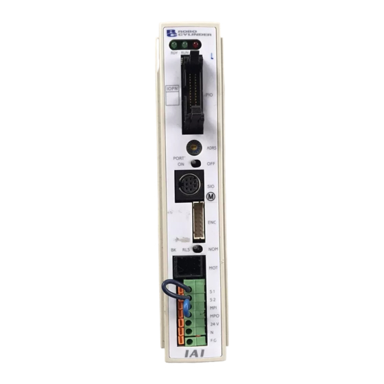
Name and Function of Each Part of the Controller 2.2.1 Names (1) Battery connector (absolute specification) (2) Status indicator LEDs RDY (green) • RUN (green) • ALM (red) (7) I/O signal connector (3) PIO pattern number label (8) Address switch (9) PORT switch (4) Teaching pendant/ PC connector... - Page 19 (5) Motor connector (MOT) A connector for the actuator’s motor power cable. (6) Power/emergency-stop terminal block [Built-in cutoff relay type RCP2-C] Provide a contact output for the emergency-stop button on the teaching pendant. Port switch ON = Emergency-stop button output (Contact B) S1, S2 Port switch OFF = ON in normal conditions of use (Emergency-stop button output is disabled)
-
Page 20: External Dimensions
External Dimensions 2.3.1 Standard Specification (RCP2-***-I An external view and dimensions of the product are shown below. φ 5 68.1... -
Page 21: Absolute Specification With Battery Bracket
2.3.2 Absolute Specification with Battery Bracket (RCP2-***-A- 62.0 69.7 35.0 φ 5 *Weight: 660 g... -
Page 22: Absolute Specification Without Battery Bracket
Absolute Specification without Battery Bracket (RCP2-***-A- 35.0 68.1 φ 5 17.5 67.0 *Weight: 460 g... -
Page 23: Installation And Noise Elimination
Installation and Noise Elimination Pay due attention to the installation environment of the controller. Installation Environment (1) When installing and wiring the controller, do not block the cooling ventilation holes. (Insufficient ventilation will not only prevent the controller from demonstrating its full performance, but it may also cause breakdown.) (2) Prevent foreign matter from entering the controller through the ventilation holes. - Page 24 Separate the controller cables from high-power lines such as a cable connecting to a power circuit. (Do not bundle together the controller cables with high-power lines or place them in the same cable duct.) When extending the supplied motor cable or encoder cable, consult IAI’s Technical Support. Noise sources and elimination Among the numerous noise sources, solenoid valves, magnet switches and relays are of particular concern when building a system.
-
Page 25: Heat Radiation And Installation
(b) DC solenoid valves, magnet switches and relays Measure: Install a diode in parallel with the coil. Determine the diode capacity in accordance with the load capacity. In a DC circuit, connecting a diode in reverse polarity will damage the diode, internal parts of the controller and/or DC power supply, so exercise due caution. -
Page 26: Wiring
Wiring Internal Drive-Power Cutoff Relay Type (RCP2-C) 4.1.1 Configuration Standard teaching pendant <RCA-T> Optional Cable length: 5 m Host system <PLC> Supplied flat cable Cable length: 2 m External unit <RCB-105-2> Cable length: 2 m Robo cylinder <RCB-105-5> Cable length: 5 m Cable length: 5 m Optional Optional... -
Page 27: External Connection Diagram
4.1.2 External Connection Diagram An example of standard wiring is shown below. Controller RCP2-C 1 (SGA) (PORT switch) 2 (SGB) 3 (+5V) Connected to teaching 5 (EMGA) pendant or PC 6 (+24V) 7 (GND) 8 (EMGB) External EMG switch Terminal block Actuator Input power supply 24 VDC... -
Page 28: Wiring The Power Supply/Emergency-Stop Switch
4.1.3 Wiring the Power Supply/Emergency-Stop Switch Wiring the power supply Input power supply 24 VDC (2 A max. per controller) To connect multiple controllers, provide a relay terminal block. Use a power cable satisfying the following specifications: Item Specification Single wire: φ1.0 / Stranded: 0.8 mm Applicable wire length , AWG size 18 Stripped wire length... - Page 29 Wiring the emergency-stop switch In many cases multiple controllers are used in a single system. To provide an emergency-stop function for the entire system, the controller circuit is designed in such a way that a single EMG switch is able to actuate an emergency stop in all connected controllers. [Internal emergency-stop circuit] Teaching pendant EMG signal...
- Page 30 Representative connection examples are explained below. Connecting the teaching pendant directly to the controller (Parallel connection with the PLC) Connecting multiple controllers (8 units or less) using a single power supply • Short the MPI and MPO terminals using a jumper wire. (The controller is shipped with these terminals shorted.) •...
- Page 31 [Controller 1] Teaching pendant EMG signal PORT switch Relay [Controller 2] Teaching pendant PORT switch Relay [Controller 3] Teaching pendant PORT switch Relay [Controller 4] Teaching pendant PORT switch Relay...
- Page 32 Using a power supply other than the input power supply (Note) Since the controller’s PORT switch has a cutoff capacity of 0.1 A, use an auxiliary relay with a coil current of 0.1 A or less and connect a diode for coil surge absorption. control [Controller 1] Teaching pendant...
- Page 33 Enabling the EMG switch on the teaching pendant for the connected axis or axes only EMG signal [Controller 1] Teaching pendant PORT switch Relay [Controller 2] Teaching pendant PORT switch Relay [Controller 3] Teaching pendant PORT switch Relay...
- Page 34 Connecting the teaching pendant to a SIO converter (Serial connection with the PLC) Configure the contact circuit for the EMG switch on the teaching pendant using EMG1/EMG2 on the power/emergency-stop terminal block on the SIO converter. (S1/S2 on the controller’s terminal block are not used.) SIO converter Teaching pendant...
-
Page 35: External Drive-Power Cutoff Relay Type
External Drive-Power Cutoff Relay Type (RCP2-CG) 4.2.1 Configuration Standard teaching pendant <RCA-T> Optional Cable length: 5 m Host system <PLC> Supplied flat cable Cable length: 2 m External unit <RCB-105-2> Cable length: 2 m Robo cylinder <RCB-105-5> Cable length: 5 m Cable length: 5 m Optional Optional... -
Page 36: External Connection Diagram
4.2.2 External Connection Diagram An example of standard wiring is shown below. Controller RCP2-CG 1 (SGA) (PORT switch) 2 (SGB) 3 (+5V) Connected to teaching 5 (EMGA) pendant or PC 6 (+24V) 7 (GND) 8 (EMGB) Terminal block Motor drive- power cutoff circuit Actuator... -
Page 37: Wiring The Power Supply/Motor Power Cutoff Relay
4.2.3 Wiring the Power Supply/Motor Power Cutoff Relay Wiring the power supply Input power supply 24 VDC (2 A max. per controller) To connect multiple controllers, provide a relay terminal block. Use a power cable satisfying the following specifications: Item Specification Single wire: φ1.0 / Stranded: 0.8 mm Applicable wire length... - Page 38 Wiring the motor power cutoff relay Explained below is a safety circuit conforming to safety category 2. The user is responsible for implementing additional safety measures in the actual circuit configuration, such as providing double contactor contacts to prevent fusing. The circuit illustrated below is for reference purposes only.
-
Page 39: Connecting The I/O Cables
Connecting the I/O Cables PIO pattern 0 [Conventional] Host system <PLC> end Controller end PIO (signal abbreviation) Upper stage Brown 1 +24 [V] Red 1 0 [V] Orange 1 Start CSTR Yellow 1 Command position 1 Green 1 Command position 2 Blue 1 Command position 4 Purple 1... -
Page 40: Pio Pattern 1 [Standard]
PIO pattern 1 [Standard] Controller end Host system <PLC> end PIO (signal abbreviation) Upper stage Brown 1 +24 [V] Red 1 0 [V] Orange 1 Command position 1 Yellow 1 Command position 2 Green 1 Command position 4 Blue 1 Command position 8 Purple 1 Gray 1... -
Page 41: Pio Pattern 2 [64-Point Positioning]
PIO pattern 2 [64-point positioning] Controller end Host system <PLC> end PIO (signal abbreviation) Upper stage Brown 1 +24 [V] Red 1 0 [V] Orange 1 Command position 1 Yellow 1 Command position 2 Green 1 Command position 4 Blue 1 Command position 8 Purple 1 PC16... -
Page 42: Pio Pattern 3 [2 Zone Output Signals]
PIO pattern 3 [2 zone output signals] Controller end Host system <PLC> end PIO (signal abbreviation) Upper stage Brown 1 +24 [V] Red 1 0 [V] Orange 1 Command position 1 Yellow 1 Command position 2 Green 1 Command position 4 Blue 1 Command position 8 Purple 1... -
Page 43: Pio Pattern 4 [Teaching]
PIO pattern 4 [Teaching] Controller end Host system <PLC> end PIO (signal abbreviation) Upper stage Brown 1 +24 [V] Red 1 0 [V] Orange 1 Command position 1 Yellow 1 Command position 2 Green 1 Command position 4 Blue 1 Command position 8 Purple 1 Operation mode... -
Page 44: Connecting The Actuator
Connecting the Actuator • Connect the motor relay cable to the MOT connector. Signal table for the controller-end connector (CN2) Pin No. Signal Wire color Description Blue Motor drive line (phase –A) Black Motor power line White Motor drive line (phase –B) Motor drive line (phase +A) Black Motor power line... - Page 45 • Connect the encoder relay cable to the ENC connector. Signal table for the controller-end connector (CN2) Pin No. Signal Description Shielded wire (Not used) (Not used) (Not used) Encoder power output Encoder control signal output (Reserved) Encoder differential signal phase-B input EN B EN B Encoder differential signal phase-A input...
- Page 46 Reference: Cable colors and pin assignments for units shipped on or before July 31, 2004 Controller end Actuator end CN2 pin assignments CN1 pin assignments CB-RCP2-PA * * * Cable color Signal name name Robot Standard Cable color (Reserved) Signal name name (Reserved)
-
Page 47: Connecting The Communication Cable
Connecting the Communication Cable Connect the communication cable to the SIO connector. Pin assignments of the cable- end connector Controller end RS485 conversion adapter end CB-RCA-SIO * * * Signal Signal Cable color Cable color name name Brown Yellow Yellow Orange Brown/Green Orange... -
Page 48: I/O Signal Control And Signal Functions
I/O Signal Control and Signal Functions PIO Patterns and Signal Assignments This controller provides five PIO (Parallel I/O) patterns to meet the needs of various applications. To select a desired PIO pattern, set a corresponding value from 0 to 4 in user parameter No. 25 (PIO pattern selection). -
Page 49: Explanation Of Signal Names
5.1.1 Explanation of Signal Names This section explains the names of signals and gives a function overview of each signal. The explanation of signal operation timings provided later on refers to the signal names. Signal Category Signal name Function overview abbreviation Input Start... -
Page 50: Signal Assignment Table For Respective Pio Patterns
5.1.2 Signal Assignment Table for Respective PIO Patterns The same signal may be assigned to a different pin number depending on the PIO pattern. Therefore, when creating a PLC sequence or wiring the signals, refer to this table to ensure each signal is assigned correctly. -
Page 51: Interface Circuit
Interface Circuit The standard interface specification of the controller is NPN, but the PNP specification is also available as an option. To prevent confusion during wiring, the NPN and PNP specifications use the same power line configuration. Accordingly, there is no need to reverse the power signal assignments for a PNP controller. 5.2.1 External Input Specifications Item... -
Page 52: External Output Specifications
5.2.2 External Output Specifications Item Specification Number of input points 10 points Rated load voltage 24 VDC Maximum current 20 mA/point Residual voltage 2V or less Insulation method Photocoupler Internal circuit configuration [NPN specification] Controller P24V Load Internal circuit Each output Load External power supply... -
Page 53: Details Of I/O Signal Functions
Details of I/O Signal Functions An input time constant is provided for the input signals of this controller, in order to prevent malfunction due to chattering, noise, etc. Except for certain signals, switching of each input signal will be effected when the signal has been received continuously for at least 6 msec. -
Page 54: Home Return (Home)
Home return (HOME) The controller will start home return operation upon detection of an OFF → ON edge of this signal. When the home return is complete, the HEND signal will be output. The HOME signal can be input as many times as required. -
Page 55: Jog (Jog+, Jog-)
Jog (JOG+, JOG-) These signals are enabled when the aforementioned MODES output signal is ON. The controller will move the actuator to the +/- soft limit upon detection of a rise (OFF → ON) edge of each JOG signal. When the soft limit is reached, the actuator will be forced to decelerate to a stop without generating an alarm. -
Page 56: Details Of Each Output Signal
5.3.2 Details of Each Output Signal Ready (SRDY) This is a monitor signal indicating that the servo is ON and the motor is ready. The ON/OFF status of the SRDY signal is synchronized with the lit/unlit status of the “RUN” LED on the front panel of the enclosure. -
Page 57: Completed Position Number (Pm1 To Pm32)
Completed position number (PM1 to PM32) These signals can be used to check the completed position number when the PEND signal turns ON. The signals are output as a binary code. Immediately after the power is input, all of the PM1 to PM32 signals are OFF. (Only with an expanded controller the binary code consists of six bits from PM1 to PM32. -
Page 58: Alarm (*Alm)
Alarm (*ALM) This signal remains ON while the controller is operating properly, and turns OFF when an alarm has generated. Provide an appropriate safety measure for the entire system by allowing the PLC to monitor the OFF status of this signal. For details of alarms, refer to 10, “Troubleshooting.”... -
Page 59: Data Entry
Data Entry <Basics> This controller doesn’t use command words, so there is no need to create a program. All you need is to enter the target position in the position-data table, and the actuator will move to the specified position. Position data consists of number (No.), target position (Position), speed (Speed), acceleration/deceleration (ACC), push (Push), positioning band (Pos. -
Page 60: Description Of Position-Data Table
Description of Position-Data Table (1) No. • Indicate the position data number. To enter an incremental movement, press the minus key in this column. On the teaching pendant, a “=” will be displayed between the number and position columns. The minus key need not be pressed in the absolute mode. (2) Target position (Position) •... - Page 61 Note: If the push force is too small, a false detection of push & hold condition may occur due to slide resistance, etc., so exercise caution. • The function of the positioning band varies depending on whether the (6) Positioning band (Pos.
-
Page 62: Relationship Of Push Force At Standstill And Current-Limiting Value
6.1.1 Relationship of Push Force at Standstill and Current-Limiting Value When performing operation in the push & hold mode, enter the current-limiting value (%) in the push column of the position-data table. Determine the current-limiting value (%) from the push force to be applied to the load at standstill. The graphs below illustrate the relationship of push force at standstill and current-limiting value for each actuator type: (1) RPA type... - Page 63 (3) RSA type Low-speed type Medium-speed type Current-limiting value (%) Current-limiting value (%) High-speed type Maximum current-limiting value Low-speed type 50% or less Medium-speed type 70% or less High-speed type 70% or less Current-limiting value (%) Note: The accuracy of push force at standstill is not guaranteed. The above graphs are provided for reference purposes only.
- Page 64 (4) RMA type Low-speed type Medium-speed type Current-limiting value (%) Current-limiting value (%) High-speed type Maximum current-limiting value Low-speed type Medium-speed type High-speed type Current-limiting value (%) Note: The accuracy of push force at standstill is not guaranteed. The above graphs are provided for reference purposes only.
-
Page 65: Explanation Of Modes
Explanation of Modes 6.2.1 Positioning Mode Push = 0 Position complete signal (1) The position complete output will turn Completed position number ON at a position preceding the target Output position by the positioning band. A completed position number signal will be output at the same time. - Page 66 Load was not contacted (missed) (1) After reaching the target position, the actuator will move at low speed (75 Completed position number rpms). Even after contacting the load, the actuator will move to the end of the Output positioning band if the stepper motor current is yet to reach the current-limiting value.
-
Page 67: Speed Change During Movement
Positioning band was entered with a wrong sign If the positioning band is entered with a wrong sign, the position will deviate by twice the positioning band, as shown to the left, so exercise due caution. Moving distance Positioning Positioning band band 6.2.3... -
Page 68: Pause
6.2.5 Pause The actuator can be paused during movement using an external input signal (*pause). The pause signal uses the contact B logic (always ON) to ensure safety. Turning OFF the *pause input will cause the actuator to decelerate to a stop, while turning it ON will allow the actuator to complete the remaining operation. -
Page 69: Zone Signal Output
6.2.6 Zone Signal Output A signal will be output when the actuator enters the specified zone. The zone signal will turn ON when the actuator enters the zone predefined by the applicable parameters. (The zone can be set arbitrarily.) Zone signal Actuator operation Zone signal setting range If parameter No. -
Page 70: Teaching Mode (Jogging/Teaching Using Pio)
6.2.8 Teaching Mode (Jogging/Teaching Using PIO) The actuator can be jogged using PIO if parameter No. 25 (PIO pattern) is set to “4: [Teaching].” The current actuator position can also be read into the controller’s position-data table using PIO. Switching between the normal positioning mode (including the push & hold mode) and the teaching mode is implemented by turning ON/OFF the operation mode input. -
Page 71: Operation
Operation <Practical Steps> How to Start 7.1.1 Standard Specification (1) Connect the motor cable and encoder cable to the controller. (2) Connect the host PLC to the PIO connector using the supplied flat cable. (3) If two or more axes are connected, set the necessary items using the address switch. For details, refer to 9, “Controlling Multiple Controllers via Serial Communication.”... - Page 72 Power ON timing Power ON *Alarm (*ALM) output RDY lamp Emergency Emergency stop is not actuated. stop (*EMGS; enabled only Motor power is not cut off. on RCP2-C controllers) ALM lamp *Pause (*STP) Pause has been cancelled. input (SON) Servo ON input RUN lamp Ready...
-
Page 73: Absolute Specification
7.1.2 Absolute Specification (1) Connect the motor cable and encoder cable to the controller. (2) Connect the host PLC to the PIO connector using the supplied flat cable. (3) If two or more axes are connected, set the address of each axis using the address switch. For details, refer to 9, “Controlling Multiple Controllers via Serial Communication.”... -
Page 74: How To Execute Home Return
How to Execute Home Return First, force the position complete signal to turn ON by referring to 7.1, “How to Start.” 7.2.1 Standard Specification When the PIO pattern is “0: [Conventional]” Select and input a desired command position number in which a target position is registered, and then input the start signal. -
Page 75: Absolute Specification
7.2.2 Absolute Specification Home return must be executed when the controller is started for the first time. Even after the home has been established, home return will become necessary if the current position is lost due to low battery voltage, etc. If the home return completion (HEND) is OFF when the power is input, check the cause and then reset the alarm to turn the alarm output (*ALM) ON. -
Page 76: Operation Timings At Pio Pattern = "0: [Conventional]
7.2.3 Operation Timings at PIO Pattern = “0: [Conventional]” (Example) 100 mm is set as the target position under position No. 3, and home position has not been established yet [Operation with the standard controller] Command position PC1 Start CSTR Position complete PEND Home return completion HEND Completed position PM1... -
Page 77: Operation Timings At Pio Pattern ≠ "0: [Conventional]
Operation Timings at PIO Pattern ≠ “0: [Conventional]” 7.2.4 Home return HOME Position complete PEND Moving MOVE Home return completion HEND Actuator movement Mechanical end Stops at the home position. Note: When the home return signal turns ON, the position complete output will turn OFF and the moving output will turn ON. -
Page 78: Home Return And Movement After Start (Home Return Not Using The Dedicated Input) (Pio Pattern = "0: [Conventional]")
Home Return and Movement after Start (PIO Pattern = “0: [Conventional]”) First, force the position complete signal to turn ON by referring to 7.1, “How to Start.” If home return has not yet been executed immediately after the system start, issuing a start command by specifying a position will cause the actuator to return to the home before moving to the specified position. - Page 79 Command position Position 1 Start Note Position complete Position 1 Completed position Home return completion Moving Positioning band Speed Actuator movement Time Mechanical end Home The position complete output will turn ON when the controller becomes ready following the power ON. (The position complete output will not turn ON if the servo ON input is OFF.) To check if the controller is ready, always check if the position complete output is ON.
-
Page 80: Positioning Mode (Back And Forth Movement Between Two Points)
Positioning Mode (Back and Forth Movement between Two Points) Example of use in operation) The actuator moves back and forth between two positions. The position 250 mm from the home is set as position 1, and the position 100 mm from the home is set as position 2. - Page 81 Position-data table (Field(s) within thick line must be entered.) Acceleration/ Acceleration Position Speed Push Positioning band deceleration only MAX Command position Position 1 Position 2 Position 1 Start Position complete Moving Note Note Note Completed position Position 1 Position 2 Position 1 Speed Actuator movement...
-
Page 82: Push & Hold Mode
Push & Hold Mode First, cause the position complete signal to turn ON by referring to 7.1, “How to Start.” Example of use in operation) The actuator is caused to move back and forth in the push & hold mode and positioning mode. - Page 83 Position-data table (Field(s) within thick line must be entered.) Acceleration/ Acceleration Position Speed Push Positioning band deceleration only MAX Command position Position 1 Position 2 Position 1 Start Position complete Moving Note Note Note Completed position Position 1 Position 2 Position 1 Speed Actuator movement...
-
Page 84: Speed Change During Movement
Speed Change during Movement Example of use in operation) The actuator speed is reduced at a certain point during movement. The position 150 mm from the home is set as position 1, and the position 200 mm from the home is set as position 2. The actuator is initially located between the home and position 1. - Page 85 Position-data table (Field(s) within thick line must be entered.) Acceleration/ Acceleration Position Speed Push Positioning band deceleration only MAX Command position Position 1 Position 2 Note Note Start Position complete Position 2 Completed position Position 1 Moving Speed Actuator movement 5 msec or more;...
-
Page 86: Operation At Different Acceleration And Deceleration Settings
Operation at Different Acceleration and Deceleration Settings Example of use in operation) Positioning is performed to the position 150 mm from the home (position 1) at a speed of 200 mm/sec. The actuator will accelerate at the maximum acceleration set according to the load, and decelerate at 0.1 G. Method) Entering “1”... - Page 87 Position-data table (Field(s) within thick line must be entered.) Acceleration/ Acceleration Position Speed Push Positioning band deceleration only MAX Command position Position 1 Start Position complete Completed position Position 1 Moving Speed Positioning band Actuator movement Acceleration at maximum 0.1 G motor torque 5 msec or more;...
-
Page 88: Pause
Pause Example of use in operation) The actuator is paused during movement. Method) Use the pause input. RCP2 controller Reference flow Select/enter a desired command position. Signal name Category (5) (2) Start Start input ON Command position 1 Command position 2 Movement to the selected position starts. - Page 89 Command position Start Note Position complete Completed position Pause Moving 4 msec or less Speed Actuator movement Deceleration to a stop Start of remaining movement 5 msec or more; time after selecting/entering a command position until the start input turns ON (The scan time of the host controller must be considered.) Note: When the start signal turns ON, the position complete output will turn OFF and the moving output will turn ON.
-
Page 90: Zone Signal Output
Zone Signal Output Example of use in operation) While the actuator is moving a zone signal is output inside the zone enclosed by distances of 40 mm and 120 mm from the home. (40 mm ≤ Zone signal output ≤ 120 mm) Method) Use the parameters “Zone boundary+”... - Page 91 Command position Note Start Position complete Completed position Zone Moving Speed Actuator movement 40 mm 120 mm 5 msec or more; time after selecting/entering a command position until the start input turns ON (The scan time of the host controller must be considered.) Note: When the start signal turns ON, the position complete output will turn OFF and the moving output will turn ON.
-
Page 92: 7.10 Incremental Moves
7.10 Incremental Moves Example of use in operation) The actuator is caused to move from the home to the 30-mm position, from which it will be moved repeatedly in increments of 10 mm. The travel speed from the home to the 30-mm position is set as 100 mm/sec, and that for 10-mm incremental moves is set as 20 mm/sec. - Page 93 Position-data table (Field(s) within thick line must be entered.) Acceleration/ Acceleration Position Speed Push Positioning band deceleration only MAX Position 1 Position 2 Command position Start Note 1 Position complete Note 2 Completed position Position 1 Position 2 Position 2 Moving Speed Actuator movement...
-
Page 94: 7.11 Notes On Incremental Mode
7.11 Notes on Incremental Mode (1) Notes on positioning operation Selecting/entering a position number using relative coordinates during positioning will cause the actuator to move to the position corresponding to the initial position plus the increment. (If the increment is a negative value, the actuator will move to the position corresponding to the initial position minus the increment.) Example) If the start signal for movement to position 2 is input while the actuator is moving to position 1, the actuator will move to the position 40 mm from the home. - Page 95 Example) If the start signal for movement to position 2 is input while the actuator is moving to position 1 in the push & hold mode, the actuator will move to the position 10 mm from where it was when the input signal was input. Position 1 Position 2 Command position...
-
Page 96: 7.12 Jogging/Teaching Using Pio
7.12 Jogging/Teaching Using PIO First, cause the position complete signal to turn ON by referring to 7.1, “How to Start.” If parameter No. 25 (PIO pattern) is set to “4: [Teaching],” the actuator can be jogged using PIO. The current actuator position can also be read into the controller’s position table using PIO. When reading the current position into the position table, all data other than position (speed, acceleration, etc.), if not already defined, will be automatically set to the default values in the applicable parameters. - Page 97 Jogging/teaching timing Operation mode (MODE) Current operation mode (MODES) +Jog (*Pause) -Jog (Reset) Position 1 Command position Current-position write (Start) (PWRT) Write completion (Position complete) (WEND) T1: 20 msec or more; time after the current-position write input is turned ON until writing of the current position is started When the operation mode (MODE) input is turned ON, the current operation mode (MODES) output will turn ON to activate the teaching mode where jogging and teaching can be performed using PIO.
-
Page 98: Parameters
Parameters Parameter Classification Parameters are classified into four types according to their content. Category: a: Parameter relating to the actuator stroke range b: Parameter relating to the actuator operating characteristics c: Parameter relating to the external interface d: Servo gain adjustment Parameter Table No. -
Page 99: Parameter Settings
Parameter Settings If a parameter has been changed, always restart the controller using a software reset command or by reconnecting the power. 8.3.1 Parameters Relating to the Actuator Stroke Range Soft limit Set the soft limit in the positive direction in parameter No. 3, and that in the negative direction in parameter No. -
Page 100: Home Return Direction
Home return direction Unless specified by the user, the home return direction is set to the motor direction at the factory. Should a need arise to change the home direction after the actuator has been assembled into your system, reverse the setting in parameter No. 5 between “0” and “1.” Also change the home return offset, if necessary. -
Page 101: Default Positioning Band (In-Position)
Default positioning band (in-position) The factory setting is “0.10 [mm].” When a target position is written to an unregistered position table or the current position is read in the teaching mode, the setting in this parameter will be used as the positioning band data for the applicable position number. -
Page 102: Current-Limiting Value At Standstill During Positioning
Current-limiting value at standstill during positioning The factory setting conforms to the standard specification of the actuator. Increasing this setting will increase the holding torque at standstill. This setting need not be changed in normal conditions of use. However, to prevent hunting caused by large external force applied while the actuator is at standstill, the value set in parameter No. -
Page 103: Pause Input Disable Selection
Pause input disable selection Parameter No. 15 defines whether the pause input signal is disabled or enabled. Set “1: [Disable]” if the pause input signal is not used, or “0: [Enable]” if the signal is used. The factory setting is “0: [Enable].” Servo ON input disable selection Parameter No. -
Page 104: Controlling Multiple Controllers Via Serial Communication
Controlling Multiple Controllers via Serial Communication This section explains the connection method to be used when multiple controllers are controlled using the PC or PLC’s communication module as the host. Basic Specifications Specification item Description Maximum number of units that can be 16 units connected Maximum cable length... -
Page 105: Sio Converter
SIO Converter This is a converter unit conforming to RS485/232C. (2) Link-connection terminal block (TB1) (1) Power/emergency-stop terminal block (TB2) (6) Monitor LEDs LED1 LED2 RS232 PORT (3) D-sub, 9-pin connector (5) PORT switch (4) Mini DIN, 8-pin connector (1) Power/emergency-stop terminal block (TB2) EMG1, EMG2 Provide a contact output for the emergency-stop switch on the teaching pendant. - Page 106 (2) Link-connection terminal block (TB1) A connection port for linking the controller. “A” on the left side connects to pin 1 (SGA) in the controller’s communication connector. “B” on the right side connects to pin 2 (SGB) in the controller’s communication connector. (Note) Be sure to use twisted pair wires for the above two connections (SGA/SGB).
-
Page 107: Address Switch
Address Switch Set an address (0 to 15) as a hexadecimal (0 to F) using the ADRS switch on the front panel of each controller to define the slave number for the controller. Assign “0” to the controller nearest the host, and then assign 1, 2, 3, …, E and F to the remaining controllers in the direction of moving away from the host. -
Page 108: Detail Connection Diagram
Detail Connection Diagram Two-paired shielded cable Recommended brand: Taiyo Electric Wire & Cable SIO converter Four-way junction (AMP: 5-1473574-4) HK-SB/20276XL 2PX22AWG EMG2 EMG1 E-Con connector (AMP: 4-1473562-4) Housing color: Green Controller link cable CB-RCB-CTL002 Yellow Yellow Orange Orange Blue Blue Controller 2 Controller 1 E-Con connector (AMP: 3-1473562-4) -
Page 109: 10. Troubleshooting
Review the events leading to the occurrence of problem, as well as the operating condition at the time of occurrence. Check the serial numbers of the controller and actuator. Analyze the cause. Take action. Please check items a) through j) before contacting IAI. (Reference) LED and output signal changes in each mode Alarm is present Emergency-stop... -
Page 110: 10.2 Alarm Level Classification
Reset each alarm after identifying and removing the cause. If the cause of the alarm cannot be removed or when the alarm cannot be reset after removing the cause, please contact IAI. If the same error occurs again after resetting the alarm, it means the cause of the alarm has... -
Page 111: 10.3 Alarm Description Output Using Pio
10.3 Alarm Description Output Using PIO So that the PLC can recognize the nature of each alarm that has generated, alarm description is output using the ports for completed position output signals (PM1 to PM8). Configure the system in such a way that the PLC can determine whether the output is a completed position number or alarm description based on the ON/OFF status of the alarm output signal (*ALM). -
Page 112: 10.4 Alarm Description And Cause/Action
10.4 Alarm Description and Cause/Action (1) Message level alarms Code Error name Cause/Action Emergency stop Cause: An emergency stop condition was detected. (This is not an error.) Motor voltage drop Cause: The “external cutoff relay” controller detected a motor drive- power cutoff condition where the MPI and MPO terminals are open. -
Page 113: Operation-Cancellation Level Alarms
Cause: Home return does not complete within the period set in the applicable system parameter after the start of home return operation. (This alarm will not generate in normal operation.) Action: The combination of controller and actuator may be wrong. Please contact IAI. - Page 114 Cause: (1) High voltage of the 24-V input power supply (2) Faulty part inside the controller Action: Check the voltage of the input power supply. If the voltage is normal, please contact IAI. Overheating This alarm indicates that the temperature around the power transistor in the controller is too high (95°C or higher).
- Page 115 Code Error name Cause/Action Absolute encoder error Cause: (1) The battery voltage was 4.4 V or below when the power was input. (2) The current position has changed due to the effect of vibration, etc., when the power was input. Action: Reset the alarm.
-
Page 116: Cold-Start Level Alarms
(5) If the load is normal, cut off the power and move the actuator by hand to check the slide resistance. If the actuator is suspected to be the cause, please contact IAI. Deviation overflow The position deviation counter has overflowed. - Page 117 Cause: (1) Malfunction due to the effect of noise, etc. (2) Faulty FPGA (3) Defective board installation inside the controller Action: Reconnect the power. If the error persists, investigate possible noise sources. If the cause cannot be specified, please contact IAI.
-
Page 118: Messages Displayed During Operation Using The Teaching Pendant Or Pc Software
10.5 Messages Displayed during Operation Using the Teaching Pendant or PC Software This section explains the warning messages that may be displayed during operation using the teaching pendant or PC software. Code Error name Cause/Action Invalid data An inappropriate value was entered in a user parameter. (Example) 9601 was entered as the serial communication speed by mistake. - Page 119 These conditions do not occur in normal operation. Should they occur, record the entire error list before cutting off the power for use in the cause investigation. Also contact IAI. No connected axis This message indicates that no controller address is recognized.
-
Page 120: 10.6 Specific Problems
Cause: (1) Reverse connection of the 24-V power supply (2) Faulty controller If the power supply is connected properly, probably the controller is faulty. Please contact IAI. (Note) If the 24-V power supply is connected in reverse, the controller may not fail immediately but its service life will likely be shortened. -
Page 121: Home Return Ends In The Middle In A Vertical Application
(2) Loosen the fixing bolts and check if the slider moves smoothly. If the slider moves smoothly, review the affixing method and bolt tightening condition. (3) If the slide resistance of the actuator itself is large, please contact IAI. Noise occurs during downward movements in a vertical application. -
Page 122: The Actuator Moves Only A Half Of, Or Twice As Much As, The Specified Movement
The lead length of the ball screw varies depending on the actuator type, so a wrong combination will cause the movement and speed to change. (2) Factory setting error at IAI Action: (1) If multiple actuators of different types must be used, confirm using the identification labels, etc., that the correct actuator is connected to the controller. -
Page 123: Appendix
Appendix * Appendix Example of Basic RCP2 Positioning Sequence Given below is an example of basic sequence for creating a positioning sequence using the RCP2. indicates PIO signals of the RCP2 controller. (Completed-position decoding circuit) Position complete PEND Waiting for the completed position to be read Timer 1 (Must be longer Completed position codes... - Page 124 Appendix (Positioning circuit for position 2) Positioning start request to position 2 Positioning start pulse to position 2 Positioning start request to position 2 Auxiliary positioning start pulse to position 2 Current positioning completed position Auxiliary positioning start for position 2 PEND Start check for position 2 Auxiliary start...
- Page 125 Appendix Command position 1 Position 3 set signal Position 5 set signal Command position 2 Position 3 set signal Position 6 set signal Command position 4 Command position 8 (Start signal circuit) Timer 2 Waiting for start 5 msec or more (Must be longer than the PLC’s scan time.)
-
Page 126: Recording Of Position-Data Table
Appendix Recording of Position-Data Table Recorded date: Speed Acceleration/ Positioning band Acceleration only Position [mm] Push [%] [mm/sec] deceleration [G] [mm]... - Page 127 Appendix Valid only when [64-point positioning] is selected Speed Acceleration/ Positioning band Acceleration only Position [mm] Push [%] [mm/sec] deceleration [G] [mm]...
-
Page 128: Recording Of User Parameters
Appendix Recording of User Parameters Recorded date: Category a: Parameter relating to the actuator stroke range b: Parameter relating to the actuator operating characteristics c: Parameter relating to the external interface d: Servo gain adjustment No. Category Name Unit Recorded data Zone boundary 1+ Zone boundary 1–... - Page 129 Ober der Röth 4, D-65824 Schwalbach am Taunus, Germany TEL 06196-88950 FAX 06196-889524 The information contained in this document is subject to change without notice for the purpose of product improvement. Copyright 2004. Jul. IAI Corporation. All rights reserved.
Need help?
Do you have a question about the RCP2 Series and is the answer not in the manual?
Questions and answers