
Subscribe to Our Youtube Channel
Related Manuals for Moxa Technologies CP-102N-T


Summary of Contents for Moxa Technologies CP-102N-T
- Page 1 Mini PCI Express Multiport Serial Board Series User Manual Version 1.0, December 2022 www.moxa.com/products © 2022 Moxa Inc. All rights reserved.
- Page 2 Mini PCI Express Multiport Serial Board Series User Manual The software described in this manual is furnished under a license agreement and may be used only in accordance with the terms of that agreement. Copyright Notice © 2022 Moxa Inc. All rights reserved. Trademarks The MOXA logo is a registered trademark of Moxa Inc.
-
Page 3: Table Of Contents
Package Checklist ..........................6 Installation Flowchart ..........................7 Hardware Installation ........................... 8 Hardware Installation Procedure ......................8 Mini PCIe Boards Dimension ........................10 CP-102N-T Dimensions ......................... 10 CP-102N-I-T Dimensions ....................... 11 CP-132N-T Dimensions ......................... 11 CP-132N-I-T Dimensions ....................... 12 CP-104N-T Dimensions ......................... 12 CP-104N-I-T Dimensions ....................... - Page 4 Device Side Pin Assignment ......................48 CP-114N-T ............................49 Board Side Pin Assignment ......................49 Device Side Pin Assignment ......................49 Troubleshooting..........................50...
-
Page 5: Introduction
1. Introduction Moxa’s Mini PCI Express serial boards meet the new slot standard for expansion boards and work with any Mini PCI Express slots. The boards have multiple RS-232/422/485 serial ports to connect data acquisition equipment and other serial devices to a PC. Overview Moxa’s new Mini PCI Express Multiport Serial Boards family fulfills a customized expansion need and provides a faster response to market. -
Page 6: Moxa Serial Comm Tool
Moxa Serial Comm Tool For application development, Moxa provides an easy-to-use serial communication library called PComm that runs under Windows operation system. Use this library to develop your own applications with Visual Basic, Visual C++, Borland Delphi, to name a few. Utilities such as View Com, Data Scope, Monitor, Terminal Emulator, and Diagnostics are included to make it easier to debug, monitor communication status, provide terminal emulation, and transfer files. -
Page 7: Installation Flowchart
Installation Flowchart The following flowchart provides a summary of the procedure you should follow to install the Mini PCI Express boards, and it provides references to chapters with more detailed information: Install the boards in PCI Express expansion Chapter 2, Hardware Installation slots. -
Page 8: Hardware Installation
Insert the Mini PCIe multiport serial board and lock the screws. Unscrew to remove the blank expansion plate. (We use Moxa V2406C as an example.) For the models (CP-102N-T, CP-102N-I-T, CP-132N-T, CP-132N-I-T, CP-104N- T) without I/O boards. Unscrew the hexagonal copper pillars on the cable (DB9 Connector) and use them to connect the provided cables with the bracket. - Page 9 Connect the Mini PCIe multiport serial board with the cables. For the models (CP-104N-I-T, CP-134N-I-T, CP-114N-T) with I/O boards. Unscrew the hexagonal copper pillars on the I/O board and lock the I/O board with the bracket. Insert the I/O board with the bracket through the blank plate hole and lock the screws. Connect the I/O board to the Mini PCIe multiport serial board with the serial cables.
-
Page 10: Mini Pcie Boards Dimension
CP-102N-I-T PCIe MUE850 CP-132N-T PCIe MUE850 CP-132N-I-T PCIe MUE850 CP-104N-T PCIe MUE850 CP-104N-I-T PCIe MUE850 CP-134N-I-T PCIe MUE850 CP-114N-T PCIe MUE850 The following content is showing the models’ dimension. CP-102N-T Dimensions Mini PCI Express Multiport Serial Board Series User Manual... -
Page 11: Cp-102N-I-T Dimensions
CP-102N-I-T Dimensions CP-132N-T Dimensions Mini PCI Express Multiport Serial Board Series User Manual... -
Page 12: Cp-132N-I-T Dimensions
CP-132N-I-T Dimensions CP-104N-T Dimensions Mini PCI Express Multiport Serial Board Series User Manual... -
Page 13: Cp-104N-I-T Dimensions
CP-104N-I-T Dimensions Mainboard Dimensions (Mini PCIe) I/O Board Dimensions Mini PCI Express Multiport Serial Board Series User Manual... -
Page 14: Cp-134N-I-T Dimensions
CP-134N-I-T Dimensions Mainboard Dimensions (Mini PCIe) I/O Board Dimensions Mini PCI Express Multiport Serial Board Series User Manual... -
Page 15: Cp-114N-T Dimensions
CP-114N-T Dimensions Mainboard Dimensions (Mini PCIe) I/O Board Dimensions Mini PCI Express Multiport Serial Board Series User Manual... -
Page 16: Software Installation
3. Software Installation In this chapter, we give installation, configuration, and update/removal procedures for the driver for Windows and Linux, proceeding with the software installation. Complete the hardware installation discussed in the previous chapter, "Hardware Installation." Refer to the next chapter, "Serial Programming Tools," for information about developing your own serial programming applications. -
Page 17: Windows 7/8 /8.1/10/11, Server 2008 R2/2012/2012 R2/ 2016 (X64)/2019/2022
Windows 7/8 /8.1/10/11, Server 2008 R2/2012/2012 R2/ 2016 (x64)/2019/2022 This section includes the following topics: Installing the Driver • Configuring the Ports • • Checking the Status • Removing the Driver Uninstalling the Driver • We will take Window 10 as an example. Its procedure is similar to the other Windows platforms regarding installing, configuring, checking the port status, removing, or uninstalling the Mini PCI Express cards. - Page 18 Please read the license agreement. If you agree, please click Next to move on. Click Next to install the driver in the indicated folder or click the Browse… button to locate a different folder. Mini PCI Express Multiport Serial Board Series User Manual...
- Page 19 Select the component (tools) you want to install. These tools are useful for configuration, monitoring, and troubleshooting. We would recommend you install it (choose the full installation). However, if you would like to install it later, please untick the box in front of the tools. Click Next when you are ready to continue.
- Page 20 Please wait until the installation is completed. This page will show all the applications that you have installed. Click Next to continue the installation process. Mini PCI Express Multiport Serial Board Series User Manual...
- Page 21 On this page, you can check the serial card default port basic configuration here. You can also click the Scan button to refresh this page. Click Next to continue the install process. 10. This is the final page for the installation process. It shows two ways to do further device configuration. One directs to the multiport serial adapters on the device manager page;...
- Page 22 Configuring the Ports After the driver has been installed, use the Device Manager to configure the serial port of your Mini PCI Express cards (the CP-114N-T will be used as an example). In this section, we describe how to access MOXA Smartio/Industio Window Driver and guide through the configuration of serial ports.
- Page 23 Configuring Serial Port You can set all parameters in the driver properties page's configuration sheet. Here is an introduction to this page. 1. FAQ: Click the FAQ button, which will open the FAQ document. If you encounter problems, please check this document before you reached out technical support.
- Page 24 2. Overview: In this section, it shows the port parameters such as COM Number, TX and RX FIFO level, and Termination Resistor. The following are the description of this parameters. Port Number and COM No. • You will need to set up all the ports of the board with the desired "COM number", which should not conflict with other COM numbers in use.
- Page 25 Port Number/Auto Enumerating COM Number Select a COM number for the port from the Port Number drop-down list. You could also type the port number in the text column to quickly get the target port. Select the Auto Enumerating COM Number option to map subsequent ports automatically. The port numbers will be assigned in sequence.
- Page 26 Serial Interface If you are using CP-132N-T, CP-132N-I-T, CP-134N-I-T, or CP-114N-T, select Interface from the drop- down list (RS-232, RS-422, RS-485-2W, or RS-485-4W). Check the Set the change to all ports option to apply the just define configuration (Interface and Bias Settings).
- Page 27 4. VM-compatible: Click this button to get the information summary of this port. Click OK to close this window. 5. Port info: Tick this setting to ignore PCI capability if this board has an transmission issue on the virtual machine. Bias Resistor Setting The termination resistor (120Ω, Enable, or Disable) and pull high/low resistor will be set by the DIP switch on the main board (CP-132N-T, CP-132-I-T).
- Page 28 Checking the Status The PComm Diagnostic program is a useful tool for checking the status of Moxa’s multiport serial boards. The program can be used to test internal and external IRQ, TxD/RxD, UART, CTS/RTS, DTR/DSR, etc. Use this program to ensure that your Moxa boards and ports are working properly. Go to start the program, click The Windows icon and find the PComm Diagnostic Program.
- Page 29 If the serial board is installed successfully, you will see the installed serial device shown on the Board Status window. Removing the Driver Open the Device Manager and put the cursor over MOXA CP-114N Series (Mini PCI Express Bus) under Multi-port serial adapters.
- Page 30 Select Delete the driver software for this device and click OK to proceed with uninstalling the board. Uninstalling the Driver The MSB driver may be removed through Add/Remove Programs in the Windows Control Panel. Open the Control Panel and click Uninstall a program. Mini PCI Express Multiport Serial Board Series User Manual...
- Page 31 Click Uninstall next to MOXA Smartio/Industio Windows Driver Verx.xx Mini PCI Express Multiport Serial Board Series User Manual...
-
Page 32: Linux Driver(32-Bit/64-Bit)
Wait until the driver has been uninstalled. Linux Driver(32-bit/64-bit) Moxa provides drivers that allow you to use the following serial boards for Linux. Mini PCI Express Boards: CP-102N-T, CP-102N-I-T, CP-132N-T, CP-132N-I-T, CP-104N-T, CP-104N-I-T, CP-134N-I-T, CP-114N-T NOTE The following procedure shows how to install the CP-114N-T driver for Linux. - Page 33 For example To set the CP-100N Series interface # muestty –i RS422 /dev/ttyMUE2 Use the Moxa diagnostics utility to verify the driver status: #cd /moxa/mxser/utility/diag #./msdiag Use the Moxa terminal utility to test the tty ports: #cd /moxa/mxser/utility/term #./msterm Mini PCI Express Multiport Serial Board Series User Manual...
-
Page 34: Serial Programming Tools
4. Serial Programming Tools Moxa provides an easy-to-use yet powerful serial programming library as well as utilities for communication troubleshooting for Windows platforms. The following sections provide details about the installation, the library, and the utilities for various platforms. Moxa PComm PComm, a professional serial communication tool for PCs, is a software package that runs under Windows NT95/98/2000/XP/2003/Vista/2008/7(x86 and x64)/8/8.1/10/11. -
Page 35: Utilities
Utilities In this section, we provide brief descriptions of each utility. For more information about these utilities, read he online help from the Documentation. Diagnostics (for Moxa boards only) This convenient diagnostics program, which only works with Moxa boards and ports, provides internal and external testing of IRQ, TxD/RxD, UART, CTS/RTS, DTR/DSR, DTR/DCD, etc. -
Page 36: Monitor
Monitor This useful port status monitoring program allows you to monitor data transmission of selected Moxa COM ports. To run the Monitor program, click the search icon and search the PComm Monitor program and then launch this program. The program monitors data transmission/reception throughput and communication line status, with data updated and displayed on the screen at regular time intervals. -
Page 37: Terminal Emulator
Terminal Emulator Use Terminal Emulator to connect to your PC’s serial ports to check if the data is transmitted correctly. To run Terminal Emulator, click the search icon and search the PComm Terminal Emulator program and then launch this program. Terminal Emulator features multi-windows and supports VT100 and ANSI terminal types. -
Page 38: Viewcom
ViewCom ViewCom is a useful tool to easily see your Moxa serial board status. ViewCom is also a shortcut to the serial boards parameter configuration page. You don’t need to go to “device manager” and find the serial boards name, which is a complicated process. ViewCom has many useful features. -
Page 39: Programming Guide
5. Programming Guide If you want to develop your own driver, no matter whether on a Windows or Linux platform, the Moxa Smartio/Industio Programming Guide is a useful instruction. The following topics are covered in this chapter: Relative Product List IRQ * 1 I/O : UART register:... -
Page 40: Uart Register Structure For Mue250, Mue450, And Mue850 Chips
UART Register Structure for MUE250, MUE450, and MUE850 Chips There are 512 bytes for each UART register and 0x200 offset between each port. However, there is one exception: for the models that are 4-port boards, such as CP-104EL-A, CP-114EL, CP-114EL-I, and CP- 134EL-A, the offset of the fourth UART register is 0xE00. -
Page 41: For Baudrate Settings
Control Serial Interface and Termination Resistor for MUE Chips For Moxa boards that use MUE250, MUE450, and MUE850 chips, BAR2, which allocates 16 bytes, is the vector base address that can be used to control serial interfaces and termination resistors, according to the following table. -
Page 42: Moxa Board Pci Device Id List
Moxa Board PCI Device ID List Model Ports Chip Max Baud Vendor ID Device ID CP-102N-T PCIe MUE850 921.6k 0x1393 0x1027 CP-102N-I-T PCIe MUE850 921.6k 0x1393 0x1027 CP-132N-T PCIe MUE850 921.6k 0x1393 0x1323 CP-132N-I-T PCIe MUE850 921.6k 0x1393 0x1323 CP-104N-T... -
Page 43: Pin Assignments
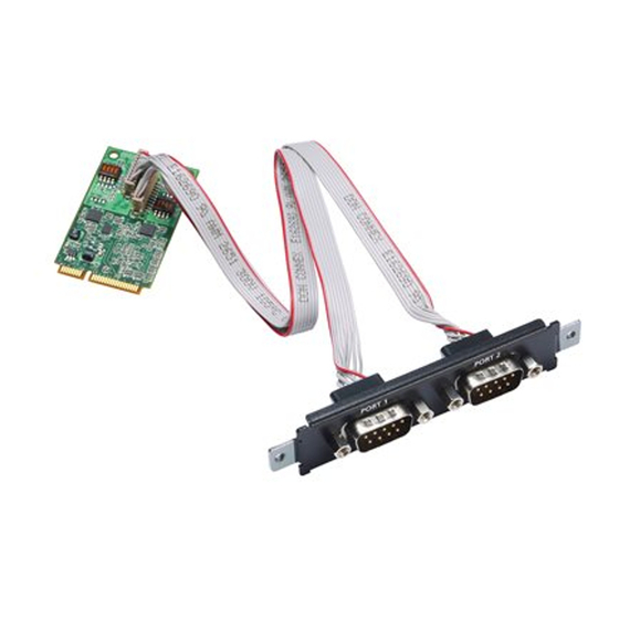
CP-114N-T CP-102N-T The CP-102N-T 2-port RS-232 Mini PCI Express serial board has two male wafer connectors on the board, with a 10-pin female wafer connector connected to the DB9 male connector via cables. Female Wafer to DB9 Connector Pin Assignments... -
Page 44: Cp-102N-I-T
CP-102N-I-T The CP-102N-T 2-port RS-232 Mini PCI Express serial board has two male wafer connectors on the board, with 10-pin female wafer connector connected to the DB9 male connector via cables. Female Wafer to DB9 Connector Pin Assignments Female Wafer Connector... -
Page 45: Cp-132N-I-T
CP-132N-I-T The CP-132N-I-T 2-port RS-422/485 Mini PCI Express serial board supports RS-422, 4-wire RS-485, and 2- wire RS-485. It has two male wafer connectors on the board, with a 10-pin female wafer connector connected to the DB9 male connector via cables. Female Wafer to DB9 Connector Pin Assignments Female Wafer Connector DB9 Male Connector... -
Page 46: Cp-104N-T
CP-104N-T The CP-104N-T 4-port RS-232 Mini PCI Express serial board supports RS-232 interface. It has two male wafer connectors on the board, with a 20-pin female wafer connector connected to the DB9 male connector via cables. Female Wafer to DB9 Connector Pin Assignments Port 1 Port 2 Female Wafer Pin... -
Page 47: Cp-104N-I-T
CP-104N-I-T The CP-104N-I-T 4-port RS-232 Mini PCI Express serial board supports RS-232 interface. It has two male wafer connectors on the board, with a 20-pin female wafer connector connected to the I/O board via cables. Board Side Pin Assignment Main Board Side I/O Board Side Female Main Board Side I/O Board Side Female... -
Page 48: Cp-134N-I-T
CP-134N-I-T The CP-134N-I-T 4-port RS-422/485 Mini PCI Express serial board supports RS-422/485 interface. It has two male wafer connectors on the board, with a 20-pin female wafer connector connected to the I/O board via cables. Board Side Pin Assignment Main Board Side I/O Board Side Female Main Board Side I/O Board Side Female... -
Page 49: Cp-114N-T
CP-114N-T Board Side Pin Assignment Main Board Side I/O Board Side female Main Board Side I/O Board Side Female Female Wafer Pin Wafer Pin Female Wafer Pin Wafer Pin Device Side Pin Assignment DB9 Male Pin RS-232 RS-422/RS-485-4W RS-485-2W TxD-(A) –... -
Page 50: Troubleshooting
7. Troubleshooting In this chapter, we discuss the common PCI Express Series problems and possible solutions. If you still have problems after reading this chapter, contact your dealer or Moxa for help, or use the Problem Report Form at the end of this manual to report problems to your dealer. 1.
Need help?
Do you have a question about the CP-102N-T and is the answer not in the manual?
Questions and answers