
Related Manuals for Aaeon RICO-3399


Summary of Contents for Aaeon RICO-3399
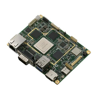
- Page 1 RICO-3399 Rockchip RK3399 Platform User’s Manual 2 Last Updated: August 27, 2020...
- Page 2 AAEON assumes no liabilities resulting from errors or omissions in this document, or from the use of the information contained herein. AAEON reserves the right to make changes in the product design without notice to its users.
- Page 3 Acknowledgement All other products’ name or trademarks are properties of their respective owners. Rockchip® is a registered trademark of Fuzhou Rockchip Electronics Co., Ltd. ⚫ Arm® and Cortex® are registered trademarks of Arm Limited (or its ⚫ subsidiaries) Android™ is a registered trademark of Google LLC ⚫...
- Page 4 Packing List Before setting up your product, please make sure the following items have been shipped: Item Quantity RICO-3399 ⚫ RTC Battery ⚫ MB Power Cable ⚫ If any of these items are missing or damaged, please contact your distributor or sales representative immediately.
- Page 5 (if any), its specifications, dimensions, jumper/connector settings/definitions, and driver installation instructions (if any), to facilitate users in setting up their product. Users may refer to the product page at AAEON.com for the latest version of this document. Preface...
- Page 6 Safety Precautions Please read the following safety instructions carefully. It is advised that you keep this manual for future references All cautions and warnings on the device should be noted. Make sure the power source matches the power rating of the device. Position the power cord so that people cannot step on it.
- Page 7 If any of the following situations arises, please the contact our service personnel: Damaged power cord or plug Liquid intrusion to the device iii. Exposure to moisture Device is not working as expected or in a manner as described in this manual The device is dropped or damaged Any obvious signs of damage displayed on the device...
- Page 8 FCC Statement This device complies with Part 15 FCC Rules. Operation is subject to the following two conditions: (1) this device may not cause harmful interference, and (2) this device must accept any interference received including interference that may cause undesired operation. This equipment has been tested and found to comply with the limits for a class B digital device, pursuant to Part 15 of the Federal Communications Commission (FCC) rules.
- Page 9 ISEDC Statement This device contains licence-exempt transmitter(s)/receiver(s) that comply with Innovation, Science and Economic Development Canada’s licence-exempt RSS(s). Operation is subject to the following two conditions: (1) This device may not cause interference. (2) This device must accept any interference, including interference that may cause undesired operation of the device.
- Page 10 China RoHS Requirement (EN/CN) Poisonous or Hazardous Substances or Elements in Products AAEON Main Board/ Daughter Board/ Backplane Poisonous or Hazardous Substances or Elements Hexavalent Polybrominated Polybrominated Component Lead Mercury Cadmium Chromium Biphenyls Diphenyl Ethers (Pb) (Hg) (Cd) (Cr(VI)) (PBB) (PBDE) PCB &...
-
Page 11: Table Of Contents
Table of Contents Chapter 1 - Product Specifications..................1 Specifications ......................2 Chapter 2 – Hardware Information ..................4 Dimensions ....................... 5 Jumpers and Connectors ..................6 List of Jumpers ......................7 2.3.1 Power Button (JP2) ..................7 2.3.2 RS-232/422/485 (D-Sub) Voltage Output Selection (JP3) ....7 2.3.3 eDP Port Voltage Selection (JP4) .............. - Page 12 2.4.16 DC Power Input (CN16)................15 2.4.19 Integrated USB, I2C x 2, 5V (CN19) ............16 2.4.21 RS-232 Port (CN21) ..................16 2.4.22 GPIO Port (CN22) ..................16 Function Block ......................17 Appendix A – Mating Connectors ..................18 List of Mating Connectors and Cables ............... 19 Preface...
-
Page 13: Chapter 1 - Product Specifications
Chapter 1 Chapter 1 - Product Specifications... -
Page 14: Specifications
Specifications System Form Factor Pico-ITX Rockchip RK3399 Cortex™-A72 Dual-core 1.8GHz and Cortex™-A53 Quad-core 1.4GHz Mali-T864 Graphics Video Decode: MPEG-1, MPEG-2, MPEG-4, H.263, H.264, H.265, VC-1, VP8, VP9, MVC Video Encode: H.264 UP to HP @ level4.1, MVC and VP8 Memory Capacity Onboard LPDDR3 2GB/4GB (Optional) Storage/SSD 16GB eMMC and Micro-SD card... - Page 15 Display HDMI HDMI (2.0) up to 4K x 2K @60Hz Up to 4K x 2K @60Hz LVDS — MIPI — RF Function Wi-Fi 802.11 b/g/n Bluetooth V4.2 + EDR Ethernet GbE x 1 USB Port USB 3.2 Gen 1 Type C OTG x 1 USB 3.2 Gen 1 (Bottom)/USB 2.0 (Top) dual port x 1 USB 2.0 Pin Header x 1 (Integrated) Serial Port...
-
Page 16: Chapter 2 - Hardware Information
Chapter 2 Chapter 2 – Hardware Information... -
Page 17: Dimensions
Dimensions Chapter 2 – Hardware Information... -
Page 18: Jumpers And Connectors
Jumpers and Connectors Bottom Chapter 2 – Hardware Information... -
Page 19: List Of Jumpers
List of Jumpers Please refer to the table below for all of the board’s jumpers that you can configure for your application Label Function Power Button RS-232/422/485 (D-Sub) Voltage Output Selection eDP Port Voltage Selection eDP Port Backlight Voltage Selection Integrated (UART/I2C/GPIO/Others) JP7/ JP8 COM port setting... -
Page 20: Edp Port Voltage Selection (Jp4)
2.3.3 (JP4) eDP Port Voltage Selection Definition +3.3V 2.3.4 (JP5) eDP Port Backlight Voltage Selection Definition +12V 2.3.5 Integrated (UART/I2C/GPIO/Others) (JP6) Definition Definition +3.3V I2C1_CLK GPIO0 UART4_TX I2C1_DATA GPIO1 GPIO2 UART4_RX GPIO3 2.3.6 COM Port Setting (JP7/JP8) Mode RS422 Open Open RS232 Open... -
Page 21: List Of Connectors
List of Connectors Please refer to the table below for all of the board’s connectors that you can configure for your application Label Function RTC Battery Connector I-PEX Connector for Wi-Fi CN3H3 mPCIe Slot for WWAN Card Nano-SIM Slot RS-232/422/485 Port (D-Sub) USB 3.2 Gen 1 (Bottom)/ USB 2.0 (Top) Dual Port USB 3.2 Gen 1 Type C OTG Debug Port... -
Page 22: Rtc Battery Connector (Cn1)
2.4.1 RTC Battery Connector (CN1) Definition +3.3V 2.4.2 (CN2) I-PEX Connector for Wi-Fi Standard specifications. 2.4.3 mPCIe Slot for WWAN Card (CN3H3) Definition Definition Definition Definition WAKE_UP USIM_RESET +3.3V +3.3V WAKE_UP_OUT DISABLE USIM_PWR RESET USIM_DATA USB1_D- +3.3V USIM_CLK USB1_D+ +3.3V +3.3V Chapter 2 –... -
Page 23: Nano-Sim Slot (Cn4)
2.4.4 Nano-SIM Slot (CN4) Definition Definition USIM_PWR USIM_RESET USIM_CLK USIM_DATA 2.4.5 RS-232/422/485 Port (D-Sub) (CN5) RS-232 Definition Definition Vout (refer to JP3) RS-485 Definition Definition RS485_D-(B) RS485_D+(A) Chapter 2 – Hardware Information... -
Page 24: Usb 3.2 Gen 1 (Bottom)/ Usb 2.0 (Top) Dual Port (Cn6)
RS-422 Definition Definition RS422_TX-(B) RS422_TX+(A) RS422_RX+(A) RS422_RX-(B) 2.4.6 (CN6) USB 3.2 Gen 1 (Bottom)/ USB 2.0 (Top) Dual Port Definition Definition USB2_D- USB3_D- USB2_D+ USB3_D+ 2.4.7 USB 3.2 Gen 1 Type C OTG (CN7) Definition OTG_USB_D- OTG_USB_D+ OTG_ID Chapter 2 – Hardware Information... -
Page 25: Debug Port (Cn8)
2.4.8 Debug Port (CN8) Definition Definition 2.4.9 Gigabit Ethernet (GbE) Port (CN9) Definition Definition TX+_D1 BI-_D3 TX-_D1 RX-_D2 RX+_D2 BI+_D4 BI+_D3 BI-_D4 Chapter 2 – Hardware Information... -
Page 26: Edp Connector (Cn11)
2.4.11 eDP Connector (CN11) Definition Definition Definition eDP_HPD eDP_TX0- LCD_PWR BKL_ENABLE eDP_TX0+ LCD_PWR BKL_CONTROL eDP_TX3- eDP_TX1- eDP_TX3+ eDP_TX1+ BKL_PWR eDP_AUX- BKL_PWR eDP_TX2- eDP_AUX+ BKL_PWR eDP_TX2+ BKL_PWR Note: For Pins 26, 27, 28 and 29 BKL_PWR, refer to JP2 for setting information 2.4.13 HDMI 2.0 Port Type A (CN13) Definition... -
Page 27: Micro-Sd Card Slot (Cn14)
2.4.14 Micro-SD Card Slot (CN14) Definition Definition DAT2 DAT3 DAT0 DAT1 +3.3V 2.4.15 Speaker Connector (CN15) Definition Definition RIGHT_OUT Spk_L_P HP_DET Spk_L_N Spk_R_P LEFT_OUT Spk_R_N 2.4.16 (CN16) DC Power Input Definition +12V Chapter 2 – Hardware Information... -
Page 28: Integrated Usb, I2C X 2, 5V (Cn19)
2.4.19 (CN19) Integrated USB, I2C x 2, 5V Definition Definition I2C4_CLK USB1_D- I2C4_DATA I2C3_CLK I2C3_DATA NFC_DFU USB1_D+ 2.4.21 RS-232 Port (CN21) Definition Definition Vout (refer to JP3) 2.4.22 GPIO Port (CN22) Definition Definition GPO0 GPI2 GPI0 GPO3 GPO1 GPI3 GPI1 +3.3V GPO2 Chapter 2 –... -
Page 29: Function Block
Function Block Chapter 2 – Hardware Information... -
Page 30: Appendix A - Mating Connectors
Appendix A Appendix A – Mating Connectors... -
Page 31: List Of Mating Connectors And Cables
List of Mating Connectors and Cables Connector Function Mating Connector Available Cable P/N Label Cable Vendor Model No RTC Battery AECS 50208-00201-001 Connector I-PEX Connector I-PEX 20279-001E Coaxial 1700010252 for Wi-Fi Cable CN3H3 mPCIe Slot for FOXCONN AS0B22x-S56Q-7H WWAN Card Nano-SIM Slot SUNFUN SMHN-SO1(01T) - Page 32 Connector Function Mating Connector Available Cable P/N Label Cable Vendor Model No CN21 RS-232 Port PINREX 712-71-09TW01 D-sub9 1701090150 console cable CN22 GPIO Port CATCH 1204-700-10SMR Appendix A – Mating Connectors...
Need help?
Do you have a question about the RICO-3399 and is the answer not in the manual?
Questions and answers