Table of Contents
Advertisement
Quick Links
This user's guide describes the setup and use of the TPS929120EVM evaluation module (EVM). This
EVM helps the user evaluate the features of the Texas Instruments TPS929120-Q1, which is an
automotive 12-channel LED driver with FlexWire interface, to address increasing needs of individual
control of each LED string. This document includes hardware setup instructions, software instructions, a
schematic diagram, a bill of materials and printed-circuit board layout drawings.
1
2
3
4
1
2
3
4
5
6
7
8
9
10
11
12
13
14
15
16
17
18
19
20
1
2
3
SLVUBM2B - April 2019 - Revised December 2019
Submit Documentation Feedback
................................................................................................................
................................................................................................
..........................................................................................................
................................................................................................................
.........................................................................................................
...................................................................................
..............................................................................................
.......................................................................................
.........................................................................................
..............................................................................................
...............................................................................
..............................................................................................
.................................................................................
..................................................................................
...................................................................................
.........................................................................................................
.........................................................................................
...................................................................................
.....................................................................................................
Copyright © 2019, Texas Instruments Incorporated
SLVUBM2B - April 2019 - Revised December 2019
TPS929120EVM User's Guide
Contents
List of Figures
..............................................................................
...........................................................................
................................................................................
.................................................................
List of Tables
User's Guide
...............................
..................................
.......................................
...........................................
TPS929120EVM User's Guide
3
3
3
15
3
4
4
5
6
7
7
8
8
9
10
11
11
12
13
14
14
15
15
17
5
6
18
1
Advertisement
Table of Contents

Related Manuals for Texas Instruments TPS929120EVM


Summary of Contents for Texas Instruments TPS929120EVM
-
Page 1: Table Of Contents
SLVUBM2B – April 2019 – Revised December 2019 TPS929120EVM User's Guide This user's guide describes the setup and use of the TPS929120EVM evaluation module (EVM). This EVM helps the user evaluate the features of the Texas Instruments TPS929120-Q1, which is an automotive 12-channel LED driver with FlexWire interface, to address increasing needs of individual control of each LED string. - Page 2 Trademarks All trademarks are the property of their respective owners. TPS929120EVM User's Guide SLVUBM2B – April 2019 – Revised December 2019 Submit Documentation Feedback Copyright © 2019, Texas Instruments Incorporated...
-
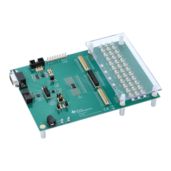
Page 3: What You Get
Figure 1. TPS929120EVM Kit What You Need In Addition The following additional items are required to run the TPS929120EVM: • PC with TPS929120EVM GUI installed or to run the on-line TPS929120EVM GUI • 12-V DC power supply How to Get Started... -
Page 4: Hardware Setup Without Can Transceiver
• Connect USB2ANY tool to PC through the USB cable. • Connect USB2ANY tool to the J3 connector of TPS929120EVM through ribbon cable. Figure 3. TPS929120EVM Jumper Configurations without TPS929120CANEVM Connected TPS929120EVM User's Guide SLVUBM2B – April 2019 – Revised December 2019 Submit Documentation Feedback Copyright ©... -
Page 5: Hardware Setup With Can Transceiver
PWM signal terminals from the USB2ANY are disconnected to such signal terminals of the TPS929120- Q1 device on the TPS929120EVM. As a result, an extra instrument for generating the PWM or clock signal is required to simulate the external PWM or clock input to TPS929120EVM, because both signal outputs from USD2ANY board are not transmitted to TPS929120EVM if TPS929120CANEVM is connected. -
Page 6: Tps929120Evm Jumper Configurations With Tps929120Canevm Connected
How to Get Started www.ti.com Figure 5. TPS929120EVM Jumper Configurations With TPS929120CANEVM Connected Table 2. TPS929120EVM Jumpers Setting with TPS929120CANEVM Connected HEADER SETTING J2, J10, J17, J19, J20, J40 Open J4, J5, J6, J8, J9, J11 Short Short “FS” to “H”... -
Page 7: Tps929120Canevm Jumper Configurations
TI Cloud Agent for the first time. Follow the steps to install the browser extension and TI Cloud Agent Applications. Figure 7. TPS929120-Q1 Gallery Page SLVUBM2B – April 2019 – Revised December 2019 TPS929120EVM User's Guide Submit Documentation Feedback Copyright © 2019, Texas Instruments Incorporated... -
Page 8: Gui And Gui Composer Download Page
Continue to click on the "Next" button to complete the GUI Composer Runtime installation. Figure 9. GUI Composer Runtime Installation After the GUI Composer installation, it continues to install the TPS929120EVM GUI. Follow the on-screen instructions by clicking the "Next" button to finish the GUI installation. Once installed, a shortcut to the GUI is found on the desktop and also in the start-up menu under the Texas Instruments folder. -
Page 9: Firmware Update Prompt Window
Figure 11 to update the firmware. After upgrading the USB2ANY firmware version to 2.8.2.0, close the USB2ANY Explorer and open the TPS929120EVM GUI again. While trying to connect the EVM board, the firmware upgrade window as showed in Figure 10 will appear. -
Page 10: Usb2Any Firmware Loader
Figure 11. USB2ANY Firmware Loader GUI Function This section provides instructions to run the TPS929120EVM using the TPS929120EVM GUI. 3.4.1 Connection Status Make sure to power up the EVM board and connect it to the PC through USB2ANY tool before opening the on-line version GUI or desktop version GUI. -
Page 11: Tps929120Evm Gui Connection Status
On the EVM board, the ADDR0, ADDR1 and ADDR2 can be configured as High or Low through "J15", "J14" and "J13" connectors. On the GUI page you can directly enter the specified value through the "Device Address" widget. Figure 12. TPS929120EVM GUI Connection Status 3.4.2 Walkthrough Wizard Prompt The GUI integrated walkthrough wizard prompts for each page to guide user through the GUI instructions. -
Page 12: Tps929120Evm Gui Quick Start Page
Once a LED open, short or single LED short-circuit occurs, the related flag becomes red under the diagnostic details panel. For detailed operation instructions, see the walkthrough wizard of this page. Figure 14. TPS929120EVM GUI Quick Start Page 3.4.4 Advanced Page Figure 15 shows the advanced page where, compared to quick start page, more functions are provided. -
Page 13: Tps929120Evm Gui Advanced Page
How to Get Started www.ti.com Figure 15. TPS929120EVM GUI Advanced Page 3.4.5 EEPROM Programming Page The device supports two programming modes for different applications: either with chip select or external address select. Figure 16 shows the EEPROM programming page. The programming mode is set as the method you have configured during sync-up process, which can also be toggled through clicking one of the programming buttons. -
Page 14: Tps929120Evm Gui Eeprom Programming Page
How to Get Started www.ti.com Figure 16. TPS929120EVM GUI EEPROM Programming Page 3.4.6 Registers Page Figure 17 shows the registers page. All the configuration and EEPROM registers are available on this page. Clicking on the row of the register automatically updates the corresponding field view on the right side of the page. -
Page 15: Board Layout
Board Layout www.ti.com Board Layout Figure 18 Figure 19 show the PCB layout of TPS929120EVM. Figure 18. Top Layer Routing Figure 19. Bottom Layer Routing (Mirrored) SLVUBM2B – April 2019 – Revised December 2019 TPS929120EVM User's Guide Submit Documentation Feedback... - Page 16 Board Layout www.ti.com Schematic Figure 20 is the TPS929120EVM schematic. TPS929120EVM User's Guide SLVUBM2B – April 2019 – Revised December 2019 Submit Documentation Feedback Copyright © 2019, Texas Instruments Incorporated...
-
Page 17: Tps929120Evm Schematic Diagram
59.0 CANL 0.5pF CANL 1000pF 1000pF 1000pF 1000pF 0.5pF CANH_CC CANL_CC TCAN1042HGDRQ1 TX_CC RX_CC 0.5pF Figure 20. TPS929120EVM Schematic Diagram SLVUBM2B – April 2019 – Revised December 2019 TPS929120EVM User's Guide Submit Documentation Feedback Copyright © 2019, Texas Instruments Incorporated... -
Page 18: Bill Of Materials (Bom)
J2, J12, J13, J14, J15 Header, 100mil, 3x1, Gold, TH PBC03SAAN Solutions Header(shrouded), 2.54mm, 5x2, Gold, Sullins Connector SBH11-PBPC-D05-RA-BK R/A, TH Solutions TPS929120EVM User's Guide SLVUBM2B – April 2019 – Revised December 2019 Submit Documentation Feedback Copyright © 2019, Texas Instruments Incorporated... - Page 19 8-Bit Bidirectional Voltage-Level Shifter For Open-Drain And Push-Pull Texas Instruments TXS0108ERGYR Application, RGY0020A (VQFN-20) 12-Channel Automotive FlexWire Texas Instruments TPS929120QPWPRQ1 Driver, PWP0024P (HTSSOP-24) SLVUBM2B – April 2019 – Revised December 2019 TPS929120EVM User's Guide Submit Documentation Feedback Copyright © 2019, Texas Instruments Incorporated...
- Page 20 Changes from A Revision (May 2019) to B Revision ...................... Page ........................• Updated Section 3.2.2 ........................• Updated Section 3.3 ........................• Updated Figure 20 Revision History SLVUBM2B – April 2019 – Revised December 2019 Submit Documentation Feedback Copyright © 2019, Texas Instruments Incorporated...
- Page 21 TI products. TI’s provision of these resources does not expand or otherwise alter TI’s applicable warranties or warranty disclaimers for TI products. TI objects to and rejects any additional or different terms you may have proposed. IMPORTANT NOTICE Mailing Address: Texas Instruments, Post Office Box 655303, Dallas, Texas 75265 Copyright © 2022, Texas Instruments Incorporated...
Need help?
Do you have a question about the TPS929120EVM and is the answer not in the manual?
Questions and answers