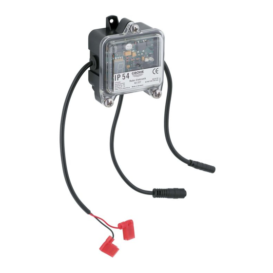
Summary of Contents for Grohe Tectron 38 386
- Page 1 38 386 Tectron ..1 ..17 ..33 ..5 ..21 ..9 DK ..25 ..13 ..29 94.473.231/ÄM 206105/01.07...
- Page 2 Bitte diese Anleitung an den Benutzer der Armatur weitergeben! Please pass these instructions on to the end user of the fitting! S.v.p remettre cette instruction à l'utilisateur de la robinetterie!
-
Page 4: Operation
EU guidelines. The conformity declarations can be obtained from the following address: Type approvals GROHE Deutschland Vertriebs GmbH The system may only be operated in the following countries: Zur Porta 9 Germany, France, Belgium, Spain, Italy, Netherlands, Denmark, D-32457 Porta Westfalica Norway, Switzerland, Austria and Portugal. -
Page 5: Final Installation
Final installation Making settings Preparations – element Setting mode 1. Remove inspection cover if necessary. In setting mode, the flow volume (see Setting the flow volume) 2. Remove structural shell protection (C), see fold-out page II, and detection zone (see Setting the range) can be checked Fig. -
Page 6: Maintenance
Setting the range Set minimum delay time (factory setting: 7 s) The range can be changed in steps. The factory-adjusted range is step 5. 1. Press the TEST button => test mode is switched on. Using the + and – buttons ( button), the minimum The range can be changed as follows: delay time can be increased (+) and reduced (–). -
Page 7: Fault/ Cause/ Remedy
IV. Sensor element V. Sensor for wall installation 1. Loosen screw (D1) and push sensor bracket (D) 1. Disconnect plug-in connector between sensor cable (E1) downwards, see Fig. [3]. and electronic module (A), see Fig. [16]. 2. Disconnect plug-in connector between sensor cable (E1) 2.


Need help?
Do you have a question about the Tectron 38 386 and is the answer not in the manual?
Questions and answers