
Subscribe to Our Youtube Channel
Related Manuals for Fibocom NL668-EAU-MiniPCIe-10


Summary of Contents for Fibocom NL668-EAU-MiniPCIe-10
- Page 1 FIBOCOM NL668-EAU&EU-MiniPCIe-10 Hardware User Manual Version: V1.0.6 Date: 2019-05-06...
- Page 2 NL668-EU-01-MiniPCIe-10 Based on NL668-EAU-00-MiniPCIe-10,delete B28 NL668-EU-00-MiniPCIe-10 Based on NL668-EU-01-MiniPCIe-10, don’t support TDD NL668-EU-03-MiniPCIe-10 Based on NL668-EU-01-MiniPCIe-10, change MCP to Reproduction forbidden without Fibocom Wireless Inc. written authorization – All Rights Reserved. FIBOCOM NL668-EAU-MiniPCIe-10 Hardware User Manual Page 2 of 56...
- Page 3 Trademark The trademark is registered and owned by Fibocom Wireless Inc. Reproduction forbidden without Fibocom Wireless Inc. written authorization – All Rights Reserved. FIBOCOM NL668-EAU-MiniPCIe-10 Hardware User Manual Page 3 of 56...
- Page 4 2019-04-29 diagram, Correct some Gaoying Tumin Tumin description Gaotianhuan Tumin Tumin V1.0.6 2019-05-06 NL668-EU-03-MiniPCIe-10 Heruzhi Lixiyi Lixiyi product description Reproduction forbidden without Fibocom Wireless Inc. written authorization – All Rights Reserved. FIBOCOM NL668-EAU-MiniPCIe-10 Hardware User Manual Page 4 of 56...
-
Page 5: Table Of Contents
UART Interface ......................27 3.6.1 UART Interface Definition ..................... 27 3.6.2 UART Interface Application ................... 28 Status Indicator ......................29 Reproduction forbidden without Fibocom Wireless Inc. written authorization – All Rights Reserved. FIBOCOM NL668-EAU-MiniPCIe-10 Hardware User Manual Page 5 of 56... - Page 6 Tray Dimension ......................50 Appendix A GPRS and EGPRS Encoding Scheme ............52 Appendix B Terms and Acronyms .................. 54 Reproduction forbidden without Fibocom Wireless Inc. written authorization – All Rights Reserved. FIBOCOM NL668-EAU-MiniPCIe-10 Hardware User Manual Page 6 of 56...
- Page 7 Figure 6-4 67910-0002 Connector ..................... 49 Figure 6-5 Tray Packaging Process ....................50 Figure 6-6 Tray Dimension (Unit: mm) ....................51 Reproduction forbidden without Fibocom Wireless Inc. written authorization – All Rights Reserved. FIBOCOM NL668-EAU-MiniPCIe-10 Hardware User Manual Page 7 of 56...
- Page 8 Table 5-5 ESD Allowable Discharge Range ..................46 Table A- 0-1 GPRS encoding scheme ....................52 Table A-0-2 Multilevel Multislot Allocation ................... 53 Reproduction forbidden without Fibocom Wireless Inc. written authorization – All Rights Reserved. FIBOCOM NL668-EAU-MiniPCIe-10 Hardware User Manual Page 8 of 56...
- Page 9 Table B-0-1 Terms and Acronyms ....................... 56 Reproduction forbidden without Fibocom Wireless Inc. written authorization – All Rights Reserved. FIBOCOM NL668-EAU-MiniPCIe-10 Hardware User Manual Page 9 of 56...
-
Page 10: Foreword
Product manufacturers need to communicate the following safety instructions to end users. In case of failure to comply with these safety rules, Fibocom will not be responsible for the consequences caused by the user’s misuse. -
Page 11: Reference Standards
(DTE - DCE) interface for Short Message Service (SMS) and Cell Broadcast Service (CBS) 1.4 Related Document FIBOCOM_EVK-GT8230-NL User Manual FIBOCOM_RF Antenna Application Design Instruction FIBOCOM_NL668 AT Command Manual Reproduction forbidden without Fibocom Wireless Inc. written authorization – All Rights Reserved. FIBOCOM NL668-EAU-MiniPCIe-10 Hardware User Manual Page 11 of 56... -
Page 12: Product Overview
GPRS: 107kbps/85.6kbps UL (multi-slot class 33) GPRS/EDGE EDGE(E-GPRS):296kbps DL/236.8kbps UL Rel.5 (multi-slot class 33) Power 3.3V~4.3V (3.8V recommended) Normal: -30°C~+75°C Temperature Extended: -40°C~+85°C Reproduction forbidden without Fibocom Wireless Inc. written authorization – All Rights Reserved. FIBOCOM NL668-EAU-MiniPCIe-10 Hardware User Manual Page 12 of 56... -
Page 13: Hardware Diagram
Figure 2-1 hardware diagram shows the main functions of the MiniPCIe module. 1-way (U)SIM card interface 1-way USB2.0 interface Sleep&wake up control Flight mode Reproduction forbidden without Fibocom Wireless Inc. written authorization – All Rights Reserved. FIBOCOM NL668-EAU-MiniPCIe-10 Hardware User Manual Page 13 of 56... - Page 14 LED status indication function External reset function 3 RF antenna interfaces(optional) PCM digital audio interface Figure 2-1 Hardware Diagram Reproduction forbidden without Fibocom Wireless Inc. written authorization – All Rights Reserved. FIBOCOM NL668-EAU-MiniPCIe-10 Hardware User Manual Page 14 of 56...
-
Page 15: Application Interface
Level Description Bias voltage 2.7V, bias resistor MIC_P Reserved 2.2K Vmax=4.3V Vmin=3.3V VBAT Module power supply Vnorm=3.8V MIC_N Reserved Reproduction forbidden without Fibocom Wireless Inc. written authorization – All Rights Reserved. FIBOCOM NL668-EAU-MiniPCIe-10 Hardware User Manual Page 15 of 56... - Page 16 USIM_RST For 3.0V (U)SIM: (U)SIM reset signal VOLmax=0.45V VOHmin=2.55V Ground Ground VILmin=-0.3V VILmax=0.6V WAKEUP_IN External device wakeup module VIHmin=1.2V Reproduction forbidden without Fibocom Wireless Inc. written authorization – All Rights Reserved. FIBOCOM NL668-EAU-MiniPCIe-10 Hardware User Manual Page 16 of 56...
- Page 17 Module wake up external device Ground Ground USB_DM USB signal DM Ground USB_DP USB signal - Vmax=4.3V VBAT Module power supply Reproduction forbidden without Fibocom Wireless Inc. written authorization – All Rights Reserved. FIBOCOM NL668-EAU-MiniPCIe-10 Hardware User Manual Page 17 of 56...
-
Page 18: Power
The power interfaces of module are shown in the following table. Pin Name Description VBAT 2,24,39,41,52 Module power supply, 3.3V ~ 4.3V, Reproduction forbidden without Fibocom Wireless Inc. written authorization – All Rights Reserved. FIBOCOM NL668-EAU-MiniPCIe-10 Hardware User Manual Page 18 of 56... -
Page 19: Power Supply
The power stability ensures the normal operation of module. The design requires special attention to the power ripple below 300mV(the circuit ESR < 100mΩ). When the module is operating in GSM mode (Burst Reproduction forbidden without Fibocom Wireless Inc. written authorization – All Rights Reserved. FIBOCOM NL668-EAU-MiniPCIe-10 Hardware User Manual... -
Page 20: Output
Paging cycle #64 frames (USB Sleep) ≤3 LTE FDD Paging cycle #128 frames (USB Sleep) ≤3 Paging cycle #256 frames (USB Sleep) Reproduction forbidden without Fibocom Wireless Inc. written authorization – All Rights Reserved. FIBOCOM NL668-EAU-MiniPCIe-10 Hardware User Manual Page 20 of 56... - Page 21 ≤430 LTE TDD Data transfer Band 41 @+23dBm Table 3-5 Power Consumption Note: USB sleep please use AT command:at+gtusbsleepen=2,0 Reproduction forbidden without Fibocom Wireless Inc. written authorization – All Rights Reserved. FIBOCOM NL668-EAU-MiniPCIe-10 Hardware User Manual Page 21 of 56...
-
Page 22: Control Signal
The reference circuit is as follows. Customers can control the RESET_N pin using the OC/OD driver circuit or button. Figure 3-4 OC/OD Reset Reference Circuit Reproduction forbidden without Fibocom Wireless Inc. written authorization – All Rights Reserved. FIBOCOM NL668-EAU-MiniPCIe-10 Hardware User Manual Page 22 of 56... -
Page 23: Usb Interface
(12Mbits/s). Refer to “Universal Serial Bus Specification 2.0” for the time slot and electrical characteristics of the module USB bus. Reproduction forbidden without Fibocom Wireless Inc. written authorization – All Rights Reserved. FIBOCOM NL668-EAU-MiniPCIe-10 Hardware User Manual Page 23 of 56... -
Page 24: Usb Interface Definition
3.5.2 (U)SIM Interface Circuit 3.5.2.1 (U)SIM Card Conncetor With Detection Signal (U)SIM design requires the use of (U)SIM card holder (Fibocom recommend: SIM016-8P-220P). We Reproduction forbidden without Fibocom Wireless Inc. written authorization – All Rights Reserved. FIBOCOM NL668-EAU-MiniPCIe-10 Hardware User Manual... - Page 25 Principles of (U)SIM card connector with card detection signal are as follows. (U)SIM card plug in, USIM_PRESENCE is high level. (U)SIM card plug out, USIM_PRESENCE is low level. Reproduction forbidden without Fibocom Wireless Inc. written authorization – All Rights Reserved. FIBOCOM NL668-EAU-MiniPCIe-10 Hardware User Manual Page 25 of 56...
-
Page 26: U)Sim Hot Plug
USIM_PRESENCE is in low level, the module detects that (U)SIM card is removed, then it will not read the (U)SIM card. Reproduction forbidden without Fibocom Wireless Inc. written authorization – All Rights Reserved. FIBOCOM NL668-EAU-MiniPCIe-10 Hardware User Manual Page 26 of 56... -
Page 27: U)Sim Design Requirements
The following table describes the main serial port pin: Pin Name Pin Num Description UART_CTS Clear transmission UART_RTS Requests transmission Reproduction forbidden without Fibocom Wireless Inc. written authorization – All Rights Reserved. FIBOCOM NL668-EAU-MiniPCIe-10 Hardware User Manual Page 27 of 56... -
Page 28: Uart Interface Application
Another level shift circuit is shown below. The input and output circuit design in the following dashed part can refer to that in the solid line part, but pay attention to the connection direction. Reproduction forbidden without Fibocom Wireless Inc. written authorization – All Rights Reserved. FIBOCOM NL668-EAU-MiniPCIe-10 Hardware User Manual... -
Page 29: Status Indicator
600ms on /600ms off Registering network (T<15S) Register network failed Slow flash 3000ms Low /75ms High Standby 3000ms on/75ms off Reproduction forbidden without Fibocom Wireless Inc. written authorization – All Rights Reserved. FIBOCOM NL668-EAU-MiniPCIe-10 Hardware User Manual Page 29 of 56... -
Page 30: Low Power Consumption Mode
If the host nonsupport USB suspend and nonsupport VBUS function, the module can enter sleep mode by disconnect USB_VBUS from the external control circuit: Sleep: Reproduction forbidden without Fibocom Wireless Inc. written authorization – All Rights Reserved. FIBOCOM NL668-EAU-MiniPCIe-10 Hardware User Manual Page 30 of 56... - Page 31 X=1, WAKEUP_IN pin is low level, module enter sleep mode) AT+CSCLK=1 command to enable sleep function. AT+GTUSBSLEEPEN=2,X command to disable USB function (X can be 0 or 1) Reproduction forbidden without Fibocom Wireless Inc. written authorization – All Rights Reserved. FIBOCOM NL668-EAU-MiniPCIe-10 Hardware User Manual Page 31 of 56...
- Page 32 If you want to use the RI signal to represent the state of the module, please refer to the AT+GTWAKE command in 《FIBOCOM AT Commands User Manual_Sleep 》 Reproduction forbidden without Fibocom Wireless Inc. written authorization – All Rights Reserved. FIBOCOM NL668-EAU-MiniPCIe-10 Hardware User Manual...
-
Page 33: Digital Audio Interface Pcm
For more sleep command description, please refer to 《FIBOCOM AT Commands User Manual_Sleep》 3.9 Digital Audio Interface PCM The module provides a digital audio interface (PCM) that enables communication with digital audio devices such as external CODECs. The interface signals include the transmission clock PCM_CLK, the frame synchronization signal PCM_SYNC, and the input and output PCM_IN/PCM_OUT. -
Page 34: Pcm Signal Description
PCM_SYNC cycle time – – t(synca) PCM_SYNC asserted time – – μs t(syncd) PCM_SYNC deasserted time – 124.5 – Reproduction forbidden without Fibocom Wireless Inc. written authorization – All Rights Reserved. FIBOCOM NL668-EAU-MiniPCIe-10 Hardware User Manual Page 34 of 56... - Page 35 – – PCM_DOUT valid Delay from PCM_CLK falling t(zdout) – – PCM_DOUT high impedance Table 3-21 CODEC Timing Parameters Reproduction forbidden without Fibocom Wireless Inc. written authorization – All Rights Reserved. FIBOCOM NL668-EAU-MiniPCIe-10 Hardware User Manual Page 35 of 56...
-
Page 36: Antenna Interface
10MHz Bandwidth, 1 RB, QPSK LTE FDD Band 3 23+1/-1.5 10MHz Bandwidth, 1 RB, QPSK Band 5 23+1/-1.5 10MHz Bandwidth, 1 RB, QPSK Reproduction forbidden without Fibocom Wireless Inc. written authorization – All Rights Reserved. FIBOCOM NL668-EAU-MiniPCIe-10 Hardware User Manual Page 36 of 56... -
Page 37: Receiving Sensitivity
10MHz Band width LTE TDD Band 40 10MHz Band width -96.5 Band 41 10MHz Band width Table 4-3 Receiving Sensitivity Note: Reproduction forbidden without Fibocom Wireless Inc. written authorization – All Rights Reserved. FIBOCOM NL668-EAU-MiniPCIe-10 Hardware User Manual Page 37 of 56... -
Page 38: Gnss Receiver
The RF connector of the module uses an I-PEX 20279 (MHF), with a dimension of 3.1*3.0*1.25mm, as shown in Figure 4-1. Reproduction forbidden without Fibocom Wireless Inc. written authorization – All Rights Reserved. FIBOCOM NL668-EAU-MiniPCIe-10 Hardware User Manual Page 38 of 56... - Page 39 Figure 4-1 RF Connector Dimension Reproduction forbidden without Fibocom Wireless Inc. written authorization – All Rights Reserved. FIBOCOM NL668-EAU-MiniPCIe-10 Hardware User Manual Page 39 of 56...
-
Page 40: Antenna Design
Polarization is the rotation direction of the electric field in the maximum radiation direction of the antenna. It is recommended to use linear polarization. 4) Radiation pattern Reproduction forbidden without Fibocom Wireless Inc. written authorization – All Rights Reserved. FIBOCOM NL668-EAU-MiniPCIe-10 Hardware User Manual Page 40 of 56... - Page 41 LTE Band 28(700): 100 MHz LTE band 38(2600): 50 MHz LTE band 40(2300): 100 MHz LTE band 41(2500): 100 MHz Reproduction forbidden without Fibocom Wireless Inc. written authorization – All Rights Reserved. FIBOCOM NL668-EAU-MiniPCIe-10 Hardware User Manual Page 41 of 56...
-
Page 42: Antenna Reference Design
U.FL-R-SMT-1 antenna connector and corresponding match adapter cable. The folllowing figure is reference design of main antenna and diversity antenna. Figure 4-4 Main and diversity Antenna Reference Circuit Reproduction forbidden without Fibocom Wireless Inc. written authorization – All Rights Reserved. FIBOCOM NL668-EAU-MiniPCIe-10 Hardware User Manual Page 42 of 56... - Page 43 Ground around antenna must be keep connect with main ground. For more design information please refer to《FIBOCOM RF Antenna Application Design Instruction》 Reproduction forbidden without Fibocom Wireless Inc. written authorization – All Rights Reserved. FIBOCOM NL668-EAU-MiniPCIe-10 Hardware User Manual Page 43 of 56...
-
Page 44: Electrical Characteristics
5.3 Electrical Characteristics of the Interface in Operating Status : logic low level; : logic high level; Signal Unit Digital input -0.3 Digital output 0.45 1.35 Reproduction forbidden without Fibocom Wireless Inc. written authorization – All Rights Reserved. FIBOCOM NL668-EAU-MiniPCIe-10 Hardware User Manual Page 44 of 56... -
Page 45: Environmental Reliability Requirements
ESD protection, the ESD issue may occur in the transport and secondary development, so developers should consider ESD protection for the final product. In addition to considering anti-static Reproduction forbidden without Fibocom Wireless Inc. written authorization – All Rights Reserved. FIBOCOM NL668-EAU-MiniPCIe-10 Hardware User Manual... - Page 46 Contact discharge VBAT, GND ±10KV ±5KV Antenna port ±8KV ±4KV Other port ±2KV ±1KV Table 5-5 ESD Allowable Discharge Range Reproduction forbidden without Fibocom Wireless Inc. written authorization – All Rights Reserved. FIBOCOM NL668-EAU-MiniPCIe-10 Hardware User Manual Page 46 of 56...
-
Page 47: Structure Specification
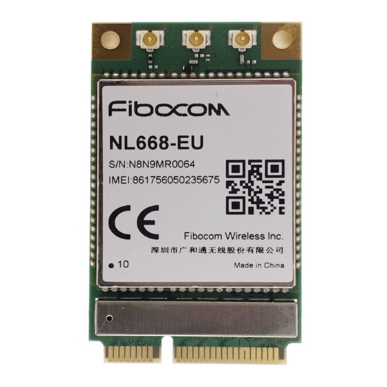
6 Structure Specification 6.1 Product Appearance The product appearance of NL668-EAU-MiniPCIe-10 module is shown in Figure 6-1: Figure 6-1 NL668-EAU-MiniPCIe-10 Module Product Appearance (Top) The product appearance of NL668-EU-MiniPCIe-10 module is shown in Figure 6-2: Figure 6-2 NL668-EU-MiniPCIe-10 Module Product Appearance (Top) Reproduction forbidden without Fibocom Wireless Inc. -
Page 48: Structure Dimension
Figure 6-3 Structure Dimension (Unit: mm) The user board can refer to the Molex’s Mini PCI Express connector, model: 67910-0002, shown as follows. Reproduction forbidden without Fibocom Wireless Inc. written authorization – All Rights Reserved. FIBOCOM NL668-EAU-MiniPCIe-10 Hardware User Manual Page 48 of 56... -
Page 49: Packaging
6.3.1 Tray Packaging Process Tray packaging process, see Figure 6-5. Reproduction forbidden without Fibocom Wireless Inc. written authorization – All Rights Reserved. FIBOCOM NL668-EAU-MiniPCIe-10 Hardware User Manual Page 49 of 56... -
Page 50: Tray Dimension
Figure 6-5 Tray Packaging Process 6.3.2 Tray Dimension The tray dimension is shown in Figure 6-5. Reproduction forbidden without Fibocom Wireless Inc. written authorization – All Rights Reserved. FIBOCOM NL668-EAU-MiniPCIe-10 Hardware User Manual Page 50 of 56... - Page 51 Figure 6-6 Tray Dimension (Unit: mm) Reproduction forbidden without Fibocom Wireless Inc. written authorization – All Rights Reserved. FIBOCOM NL668-EAU-MiniPCIe-10 Hardware User Manual Page 51 of 56...
-
Page 52: Appendix A Gprs And Egprs Encoding Scheme
Active timeslots indicates the total number of timeslots that the GPRS device can use for both uplink and downlink communications. Multislot Class Downlink Slots Uplink Slots Active Slots Reproduction forbidden without Fibocom Wireless Inc. written authorization – All Rights Reserved. FIBOCOM NL668-EAU-MiniPCIe-10 Hardware User Manual Page 52 of 56... - Page 53 89.6kbps 179.2kbps MCS-8 8-PSK 54.4kbps 108.8kbps 217.6kbps MCS-9 8-PSK 59.2kbps 118.4kbps 236.8kbps Table A-0-3 EGPRS Modulation And encoding Method Reproduction forbidden without Fibocom Wireless Inc. written authorization – All Rights Reserved. FIBOCOM NL668-EAU-MiniPCIe-10 Hardware User Manual Page 53 of 56...
-
Page 54: Appendix B Terms And Acronyms
Secondary Cell for CA Mobile Equipment Mobile Station Mobile Terminated Printed Circuit Board Protocol Data Unit Phase Shift Keying Reproduction forbidden without Fibocom Wireless Inc. written authorization – All Rights Reserved. FIBOCOM NL668-EAU-MiniPCIe-10 Hardware User Manual Page 54 of 56... - Page 55 Maximum Input High Level Voltage Value VIHmin Minimum Input High Level Voltage Value VILmax Maximum Input Low Level Voltage Value Reproduction forbidden without Fibocom Wireless Inc. written authorization – All Rights Reserved. FIBOCOM NL668-EAU-MiniPCIe-10 Hardware User Manual Page 55 of 56...
- Page 56 Minimum Output Low Level Voltage Value VSWR Voltage Standing Wave Ratio WCDMA Wideband Code Division Multiple Access Table B-0-1Terms and Acronyms Reproduction forbidden without Fibocom Wireless Inc. written authorization – All Rights Reserved. FIBOCOM NL668-EAU-MiniPCIe-10 Hardware User Manual Page 56 of 56...
Need help?
Do you have a question about the NL668-EAU-MiniPCIe-10 and is the answer not in the manual?
Questions and answers