Table of Contents
Advertisement
Advertisement
Table of Contents

Related Manuals for Fibocom L610 MiniPCIe Series


Summary of Contents for Fibocom L610 MiniPCIe Series
- Page 1 FIBOCOM L610 MiniPCIe Series Hardware Guide Version: V1.0.2 Date: 2020-06-16...
- Page 2 WIFI-Scan and BT; MiniPCIe package For the Latin America market, without diversity, with WIFI- L610-LA-00-MiniPCIe-10-00 Scan and BT; MiniPCIe package Reproduction forbidden without Fibocom Wireless Inc. written authorization - All rights reserved. FIBOCOM L610 MiniPCIe Series Hardware Guide Page 2 of 51...
- Page 3 Trademark The trademark is registered and owned by Fibocom Wireless Inc. Reproduction forbidden without Fibocom Wireless Inc. written authorization - All rights reserved. FIBOCOM L610 MiniPCIe Series Hardware Guide Page 3 of 51...
- Page 4 Added analog audio description He Jiazhao Wang Wang 2020- Yuanguang Liu Ke V1.0.0 Initial version Liuxia 03-21 Wang Bo Reproduction forbidden without Fibocom Wireless Inc. written authorization - All rights reserved. FIBOCOM L610 MiniPCIe Series Hardware Guide Page 4 of 51...
-
Page 5: Table Of Contents
UART Interface Definition ................... 26 3.6.2 UART Interface Application ..................27 Status Indicator ......................28 3.7.1 LPG Signal ......................... 28 Reproduction forbidden without Fibocom Wireless Inc. written authorization - All rights reserved. FIBOCOM L610 MiniPCIe Series Hardware Guide Page 5 of 51... - Page 6 6.3.1 Tray Packaging Process ..................... 47 6.3.2 Tray Size ........................48 Appendix ........................... 49 A. Abbreviations ........................49 Reproduction forbidden without Fibocom Wireless Inc. written authorization - All rights reserved. FIBOCOM L610 MiniPCIe Series Hardware Guide Page 6 of 51...
-
Page 7: Foreword
This document describes the electrical characteristics, RF performance, structural dimensions, and application environment of the L610 MiniPCIe series module. With the help of this document and other related documents, application developers can quickly understand the hardware functions of the L610 MiniPCIe module and develop product hardware. -
Page 8: Reference Standards
1.4 Related Documents FIBOCOM EVK-GT8230-NL User Guide FIBOCOM Design Guide_RF Antenna FIBOCOM L610 Series AT Commands Reproduction forbidden without Fibocom Wireless Inc. written authorization - All rights reserved. FIBOCOM L610 MiniPCIe Series Hardware Guide Page 8 of 51... -
Page 9: Product Overview
2 Product Overview 2.1 Introduction The L610 MiniPCIe series module is a broadband wireless terminal product applicable to multiple network formats such as FDD-LTE or TDD-LTE and GSM. Band L610-CN-00-MiniPCIe-10-00 L610-EU-00-MiniPCIe-10-00 LTE FDD Band 1, 3, 5, 8 Band 1, 3, 7, 8, 20, 28... -
Page 10: Hardware Diagram
3GPP specifications. 2.3 Hardware Diagram The main functions supported by the L610 MiniPCIe series module are shown as below, and also in figure 2-1: One (U)SIM card interface ... - Page 11 Mini PCI Express Interface CODEC L610-CN Antenna Antenna Antenna interface interface interface Main antenna GNSS WIFI Figure 2-1 Hardware diagram Reproduction forbidden without Fibocom Wireless Inc. written authorization - All rights reserved. FIBOCOM L610 MiniPCIe Series Hardware Guide Page 11 of 51...
-
Page 12: Application Interface
3 Application Interface 3.1 PCI Express Mini Card Interface The L610 MiniPCIe series module uses PCI express Mini Card interface, with a total of 52 pins. 3.1.1 Pin Distribution Figure 3-1 Pin distribution 3.1.2 Pin Definition The pin definition is shown in the following table. - Page 13 For 3.0 V (U)SIM: VOLmax=0.45 V VOHmin=2.55 V For 1.8 V (U)SIM: USIM_RST VOLmax=0.45 V (U)SIM reset signal VOHmin=1.35 V Reproduction forbidden without Fibocom Wireless Inc. written authorization - All rights reserved. FIBOCOM L610 MiniPCIe Series Hardware Guide Page 13 of 51...
- Page 14 VIHmax=2.0 V Ground Ground VILmin=-0.3 V VILmax=0.6 V DBG_UART_RX DEBUG serial port receives data VIHmin=1.2 V VIHmax=2.0 V Ground Reproduction forbidden without Fibocom Wireless Inc. written authorization - All rights reserved. FIBOCOM L610 MiniPCIe Series Hardware Guide Page 14 of 51...
- Page 15 VIHmax=2.0 V VOLmax=0.45 V DEBUG serial port transmits DBG_UART_TX VOHmin=1.35 V data *PCM_OUT VOLmax=0.45 V PCM data output Reproduction forbidden without Fibocom Wireless Inc. written authorization - All rights reserved. FIBOCOM L610 MiniPCIe Series Hardware Guide Page 15 of 51...
-
Page 16: Power Supply
43 and 50 3.2.1 Power Supply The L610 MiniPCIe series module needs to be powered by the VBAT pin. The power design is shown in figure 3-2. Reproduction forbidden without Fibocom Wireless Inc. written authorization - All rights reserved. FIBOCOM L610 MiniPCIe Series Hardware Guide... - Page 17 Figure 3-2 Power design The filter capacitor design of the L610 MiniPCIe series module power supply is described in the following table. Table 3-3 Filter capacitor design for power supply Recommended Application Introduction Capacitance To reduce power fluctuations during module operation, low ESR capacitors are required.
-
Page 18: Output
1.89 3.2.3 Power Consumption The power consumption of the L610 MiniPCIe series module under 3.8 V power supply is shown in the following table. Reproduction forbidden without Fibocom Wireless Inc. written authorization - All rights reserved. FIBOCOM L610 MiniPCIe Series Hardware Guide... - Page 19 LTE TDD LTE TDD Data transfer Band 40 @+23 dBm LTE TDD Data transfer Band 41 @+23 dBm Reproduction forbidden without Fibocom Wireless Inc. written authorization - All rights reserved. FIBOCOM L610 MiniPCIe Series Hardware Guide Page 19 of 51...
-
Page 20: Control Signals
3.3 Control Signals The L610 MiniPCIe series module provides one control signal to reset the module. The pin definition is described in the following table. Table 3-6 Reset control signal Pin Name I/O Pin Description When the module is working, pull down the RESET_N pin greater than or equal RESET_N to 100 ms then release, the module resets. -
Page 21: Reset_N Control Timing
PCB and the surface layer (to avoid module reset caused by ESD). 3.4 USB Interface The L610 MiniPCIe series module supports USB 2.0, and compatible with USB High-Speed (480 Mbit/s) and USB Full-Speed (12 Mbit/s). For details about the timing and electrical characteristics for the USB interface, see Universal Serial Bus Specification 2.0. -
Page 22: Usb Interface Definition
3.4.2 USB Upgrade If the L610 MiniPCIe series module needs to be upgraded directly with USB, please fly out the pin 7 (VDD_EXT) and pin 115 (USB_BOOT) modules, short connect the pin 7 and pin 115 to enter the download mode before booting. -
Page 23: U)Sim Interface Circuit
(U)SIM design requires (U)SIM card slot (recommended model: SIM016-8P-220P). It is recommended to use a hot plug card slot with (U)SIM detection function. Figure 3-7 SIM card slot SIM016-8P-220P Reproduction forbidden without Fibocom Wireless Inc. written authorization - All rights reserved. FIBOCOM L610 MiniPCIe Series Hardware Guide Page 23 of 51... -
Page 24: U)Sim Card Slot Without Detection Signal
For (U)SIM card slot with no detection signal, USIM_ PRESENCE strings 10 K resistance to ground, and disable the hot plug detection function by AT commands. Reproduction forbidden without Fibocom Wireless Inc. written authorization - All rights reserved. FIBOCOM L610 MiniPCIe Series Hardware Guide... -
Page 25: U)Sim Hot Plug
3.5.3 (U)SIM Hot Plug The L610 MiniPCIe series module supports the (U)SIM card hot plug function. The module determines whether the (U)SIM card is inserted or removed by detecting the pin status of USIM_ PRESENCE. The (U)SIM card hot plug function can be configured through the AT+MSMPD command. The AT command is described in the following table. -
Page 26: Uart Interface
3.6.1 UART Interface Definition The L610 MiniPCIe series module has two serial ports: main serial port and debug serial port. The following describes the main features of these two serial ports: the main serial port supports 4800bps, 9600bps, 19200bps, 38400bps, 57600bps, 115200bps, 230400bps, and 1000000bps baud rate, the default baud rate is 115200bps, used for data and AT command transmission. -
Page 27: Uart Interface Application
UART Interface Application The serial port level of the L610 MiniPCIe series module is 1.8 V. If the client host system level is 3.4 V or other, you need to add a level converter to the serial port connection between the module and the host. -
Page 28: Status Indicator
3.7 Status Indicator The L610 MiniPCIe series module provides one signal to display the operating status of the module. The following table describes the status indication pin. Table 3-14 Status indication Pin Name Description NET_MODE Module status indication 3.7.1 LPG Signal The L610 MiniPCIe series module provides a network LED interface NET_MODE. -
Page 29: Low Power Consumption Mode
Table 3-16 Flight mode control Pin Name Description W_DISABLE# Module flight mode control The L610 MiniPCIe series module supports two ways to enter the flight mode, as shown in the following table. Table 3-17 Ways for the module to enter flight mode AT+WDISABLEEN=1 Send enable W_DISABLE#. -
Page 30: Pcm Interface Description
(falling edge sampling) The L610 MiniPCIe series module is configured as above, if you need to adjust the configuration, please contact technical support. 3.9.2 PCM Signal Description The main chip of the L610 MiniPCIe series module provides PCM signals using the domestic mainstream European E1 standard. - Page 31 PCM_CLK rising t(pdout) – – PCM_DOUT valid Delay from PCM_CLK falling t(zdout) – – PCM_DOUT high impedance Reproduction forbidden without Fibocom Wireless Inc. written authorization - All rights reserved. FIBOCOM L610 MiniPCIe Series Hardware Guide Page 31 of 51...
-
Page 32: Analog Audio Interface
When using an external PA, Class-AB output is required. The recommended model is AW87359FCR (8Ω 2 W). Reproduction forbidden without Fibocom Wireless Inc. written authorization - All rights reserved. FIBOCOM L610 MiniPCIe Series Hardware Guide Page 32 of 51... -
Page 33: Preventing Tdd And Other Noises
The microphone channel reference circuit is shown in the following figure. Reproduction forbidden without Fibocom Wireless Inc. written authorization - All rights reserved. FIBOCOM L610 MiniPCIe Series Hardware Guide Page 33 of 51... -
Page 34: Speaker Interface Circuit
Figure 3-15 Microphone channel reference circuit 3.10.5 Speaker Interface Circuit Figure 3-16 SPK output reference circuit Reproduction forbidden without Fibocom Wireless Inc. written authorization - All rights reserved. FIBOCOM L610 MiniPCIe Series Hardware Guide Page 34 of 51... - Page 35 It is recommended to use differential signal mode for analog voice to ensure efficient and EMS propagation of data. Reproduction forbidden without Fibocom Wireless Inc. written authorization - All rights reserved. FIBOCOM L610 MiniPCIe Series Hardware Guide Page 35 of 51...
-
Page 36: Rf Interface
4 RF Interface The L610 MiniPCIe series module provides a MAIN antenna interface for sending and receiving RF signals. The operating band of the antenna is shown in the following table. Table 4-1 Operating band Operating Description Mode Tx (MHz) -
Page 37: Transmit Power
Transmit Power The transmission power of each frequency band of the L610 MiniPCIe series module is shown in the following table. Table 4-2 Transmit power Mode Band Tx Power (dBm) Note GSM 900 33±2 30±2 DCS 1800 33±2 GSM 850 30±2... -
Page 38: Receiving Sensitivity
Receiving Sensitivity The sensitivity of each frequency band of the L610 MiniPCIe series module is shown in the following table. Table 4-3 Receiving sensitivity Rx Sensitivity (dBm) Mode Band Note Typical -109 GSM 900 BER < 2.43% -108 DCS 1800 BER <... - Page 39 4-1. Figure 4-1 Dimensional drawing of RF connector Figure 4-2 Coaxial RF connector snapped into the RF connector Reproduction forbidden without Fibocom Wireless Inc. written authorization - All rights reserved. FIBOCOM L610 MiniPCIe Series Hardware Guide Page 39 of 51...
-
Page 40: Antenna Design
To ensure the high performance of the module, the interference must be well controlled. Suggestions: For example, LCD, CPU, FPC wiring, audio circuit and power supply should be as far as Reproduction forbidden without Fibocom Wireless Inc. written authorization - All rights reserved. FIBOCOM L610 MiniPCIe Series Hardware Guide... - Page 41 > 33 dBm (2 W) peak power GSM Input power > 23 dBm average power LTE Recommended SWR ≤ 2:1 Reproduction forbidden without Fibocom Wireless Inc. written authorization - All rights reserved. FIBOCOM L610 MiniPCIe Series Hardware Guide Page 41 of 51...
-
Page 42: Electrical Characteristics
The limit voltage range refers to the maximum voltage range that the module power supply voltage, digital and analog input/output interfaces can withstand. Working outside this range may cause damage to this product. The limit voltage range of the L610 MiniPCIe series module is shown in the following table. Table 5-1 Limit voltage range Parameter... -
Page 43: Electrical Characteristics Of The Interfaces In Operating State
Temperature +85℃±3℃, humidity 90 to 95% RH, lasting 24 hours in shutdown state high humidity test Low temperature Temperature -30℃±3℃, lasting 24 hours in operating status operation test Reproduction forbidden without Fibocom Wireless Inc. written authorization - All rights reserved. FIBOCOM L610 MiniPCIe Series Hardware Guide Page 43 of 51... -
Page 44: Esd Characteristics
5.5 ESD Characteristics The L610 MiniPCIe series module is a consumer terminal product. Although the ESD problem has been considered and ESD protection has been completed in the module design, ESD problems may also occur in transportation and secondary development, so developers should consider the protection of ESD in the final product. -
Page 45: Structure Specifications
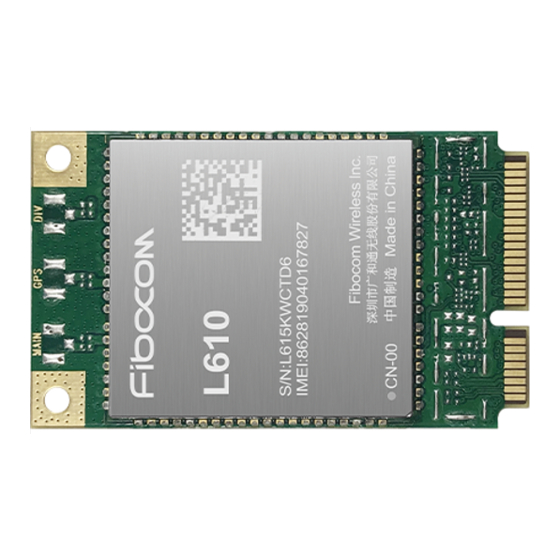
6.1 Product Appearance The appearance of the L610 MiniPCIe series module is shown in figure 6-1. Figure 6-1 Module product appearance There are three antenna interfaces in figure 6-1. The L610 MiniPCIe series module only supports the main antenna. Structure Dimension The structural dimensions of the L610 MiniPCIe series module are shown in figure 6-2. - Page 46 The user board can use Molex's Mini PCI Express connector of model 67910-0002, as shown in the following figure. Figure 6-3 67910-0002 connector Reproduction forbidden without Fibocom Wireless Inc. written authorization - All rights reserved. FIBOCOM L610 MiniPCIe Series Hardware Guide Page 46 of 51...
-
Page 47: Package
6.3 Package The L610 MiniPCIe series module adopts the tray sealed vacuum packaging, combined with the outer packaging method using the hard cartoon box, which can protect the storage, transportation and use of the module to the maximum extent. Desiccant is included in the vacuum packaging bag. The module is a moisture sensitive device with a humidity sensitivity level of 3, which complies with the regulations of the American Joint Electron Device Engineering Council (JEDEC). -
Page 48: Tray Size
6 boxes are packed in each case, as shown in figure 6-5. Figure 6-5 Tray size (unit: mm) Reproduction forbidden without Fibocom Wireless Inc. written authorization - All rights reserved. FIBOCOM L610 MiniPCIe Series Hardware Guide Page 48 of 51... -
Page 49: Appendix
Long Term Evolution SCell Secondary Cell for CA Mobile Equipment Mobile Station Mobile Terminated Printed Circuit Board Protocol Data Unit Reproduction forbidden without Fibocom Wireless Inc. written authorization - All rights reserved. FIBOCOM L610 MiniPCIe Series Hardware Guide Page 49 of 51... - Page 50 Vmin Minimum Voltage Value VIHmax Maximum Input High Level Voltage Value VIHmin Minimum Input High Level Voltage Value Reproduction forbidden without Fibocom Wireless Inc. written authorization - All rights reserved. FIBOCOM L610 MiniPCIe Series Hardware Guide Page 50 of 51...
- Page 51 VOLmin Minimum Output Low Level Voltage Value VSWR Voltage Standing Wave Ratio WCDMA Wideband Code Division Multiple Access Reproduction forbidden without Fibocom Wireless Inc. written authorization - All rights reserved. FIBOCOM L610 MiniPCIe Series Hardware Guide Page 51 of 51...
Need help?
Do you have a question about the L610 MiniPCIe Series and is the answer not in the manual?
Questions and answers