
Related Manuals for Fibocom L830-EB


Summary of Contents for Fibocom L830-EB
- Page 1 L830-EB Hardware User Manual Version: V1.0.3 Update date: 2017.06.26 Reproduction forbidden without Fibocom Wireless Inc. written authorization - All Rights Reserved. L830-EBHardware User Manual Page 1 of 39...
- Page 2 Applicability Table Product model Description L830-EB-11 Reproduction forbidden without Fibocom Wireless Inc. written authorization - All Rights Reserved. L830-EB Hardware User Manual Page 2 of 39...
- Page 3 Update RF band support,Modify I2S support 1. Modify timing diagram V1.0.3 2017-06-24 2. Update power consumption and RF performance data Reproduction forbidden without Fibocom Wireless Inc. written authorization - All Rights Reserved. L830-EB Hardware User Manual Page 3 of 39...
-
Page 4: Table Of Contents
3.5.2 USIM Interface Circuit ......................23 3.5.2.1 N.C. SIM Card Slot ....................23 3.5.2.2 N.O. SIM Card Slot ....................24 3.5.3 USIM Hot-Plugging ......................24 Reproduction forbidden without Fibocom Wireless Inc. written authorization - All Rights Reserved. L830-EB Hardware User Manual Page 4 of 39... - Page 5 5.5 Storage ............................37 5.5.1 Storage Life ......................... 37 5.6 Packing ............................37 5.6.1 Tray Package ........................38 5.6.2 Tray size ..........................39 Reproduction forbidden without Fibocom Wireless Inc. written authorization - All Rights Reserved. L830-EB Hardware User Manual Page 5 of 39...
-
Page 6: Preface
The document describes the electrical characteristics, RF performance, dimensions and application environment, etc. of L830-EB (hereinafter referred to as L830). With the assistance of the document and other instructions, the developers can quickly understand the hardware functions of L830 modules and develop products. -
Page 7: Overview
Weight: About 5.8 g Interface WWAN Main Antenna x 1 Antenna WWAN Diversity Antenna x 1 Function Interface USIM 3V/1.8V Reproduction forbidden without Fibocom Wireless Inc. written authorization - All Rights Reserved. L830-EB Hardware User Manual Page 7 of 39... -
Page 8: Application Framework
The peripheral applications for L830 module are shown in Figure 2-1: Div/GNSS ANT Main ANT Module Power Supply ON/OFF# RESET# EINT Indicator Host application Control Card Figure2-1 Application Framework Reproduction forbidden without Fibocom Wireless Inc. written authorization - All Rights Reserved. L830-EB Hardware User Manual Page 8 of 39... -
Page 9: Hardware Framework
3 Application Interface 3.1 M.2 Interface The L830 module uses standard M.2 Key-B interface, with a total of 75 pins. Reproduction forbidden without Fibocom Wireless Inc. written authorization - All Rights Reserved. L830-EB Hardware User Manual Page 9 of 39... -
Page 10: Pin Map
3.1.1 Pin Map Figure 3-1 Pin Map Note: Pin “Notch” represents the gap of the gold fingers. Reproduction forbidden without Fibocom Wireless Inc. written authorization - All Rights Reserved. L830-EB Hardware User Manual Page 10 of 39... -
Page 11: Pin Definition
Not connected, L830 M.2 module is 21 CONFIG_0 configured as the WWAN-SSIC 0 interface type. 22 I2S_RX I2S serial data input CMOS 1.8V Reproduction forbidden without Fibocom Wireless Inc. written authorization - All Rights Reserved. L830-EB Hardware User Manual Page 11 of 39... - Page 12 43 NC 44 GNSS_IRQ Reserved CMOS 1.8V 45 GND Power Supply 46 SYSCLK 26MHz clock output 1.8V 47 NC Reproduction forbidden without Fibocom Wireless Inc. written authorization - All Rights Reserved. L830-EB Hardware User Manual Page 12 of 39...
- Page 13 External reset input signal, internal 67 RESET# CMOS 1.8V 100KΩ pull-up. 68 NC 69 CONFIG_1 Connected to internal GND, L830 Reproduction forbidden without Fibocom Wireless Inc. written authorization - All Rights Reserved. L830-EB Hardware User Manual Page 13 of 39...
-
Page 14: Power Supply
The unused pins can be left floating. 3.2 Power Supply The power interface of L830 module as shown in the following table: Reproduction forbidden without Fibocom Wireless Inc. written authorization - All Rights Reserved. L830-EB Hardware User Manual Page 14 of 39... -
Page 15: Power Supply
The stable power supply can ensure the normal operation of L830 module; and the ripple of the power supply should be less than 300mV in design. When the module operates with the maximum emission Reproduction forbidden without Fibocom Wireless Inc. written authorization - All Rights Reserved. L830-EB Hardware User Manual... -
Page 16: Logic Level
3.2.3 Power Consumption In the condition of 3.3V power supply, the L830 power consumption as shown in the following table: Reproduction forbidden without Fibocom Wireless Inc. written authorization - All Rights Reserved. L830-EB Hardware User Manual Page 16 of 39... -
Page 17: Control Signal
FULL_CARD_P High: Power on 3.3V/1.8V OWER_OFF# Low or floating: Power off Reset signal, internal 100KΩ pull-up, RESET# 1.8V active low. Reproduction forbidden without Fibocom Wireless Inc. written authorization - All Rights Reserved. L830-EB Hardware User Manual Page 17 of 39... -
Page 18: Module Start-Up
Automatically start-up when powered on, and the circuit design is shown in Figure 3-5: Figure 3-4 Circuit for Module Start-up Controlled by AP Figure 3-5 Circuit for Automatic Start-up Reproduction forbidden without Fibocom Wireless Inc. written authorization - All Rights Reserved. L830-EB Hardware User Manual Page 18 of 39... -
Page 19: Start-Up Timing Sequence
5s). In the finalization process, the module will save the network, SIM Reproduction forbidden without Fibocom Wireless Inc. written authorization - All Rights Reserved. L830-EB Hardware User Manual Page 19 of 39... -
Page 20: Hardware Shutdown
Figure 3-8: +3.3V RESET# FULL_CARD_POWER_OFF# ≥100ms VSD2_1V8 ≥ 10ms Module State Activation PMU RESET Figure 3-8 Hardware Shutdown Timing Control Reproduction forbidden without Fibocom Wireless Inc. written authorization - All Rights Reserved. L830-EB Hardware User Manual Page 20 of 39... -
Page 21: Module Reset
GND. Also, the RESET# signal lines shall neither near the PCB edge nor route on the surface planes to avoid module from reset caused by ESD problems. Reproduction forbidden without Fibocom Wireless Inc. written authorization - All Rights Reserved. L830-EB Hardware User Manual... -
Page 22: Usb Interface
USB_D- and USB_D+ signal lines should be routed on the layer that is adjacent to the ground layer, and wrapped with GND vertically and horizontally. Reproduction forbidden without Fibocom Wireless Inc. written authorization - All Rights Reserved. L830-EB Hardware User Manual... -
Page 23: Usim Interface
The reference circuit design for N.C. (Normally Closed) SIM card slot is shown in Figure 3-12: Figure 3-12 Reference Circuit for N.C. SIM Card Slot Reproduction forbidden without Fibocom Wireless Inc. written authorization - All Rights Reserved. L830-EB Hardware User Manual Page 23 of 39... -
Page 24: Sim Card Slot
AT command as shown in the following table: AT Command Hot-plugging Detection Function Description AT+MSMPD=1 Enable Default value, the SIM card hot-plugging detection function Reproduction forbidden without Fibocom Wireless Inc. written authorization - All Rights Reserved. L830-EB Hardware User Manual Page 24 of 39... -
Page 25: Usim Design
The filter capacitors and ESD devices for SIM card signals should be placed near to the SIM card slot, and the ESD devices with 22~33pF capacitance should be used. Reproduction forbidden without Fibocom Wireless Inc. written authorization - All Rights Reserved. L830-EB Hardware User Manual... -
Page 26: Status Indicator
Figure 3-14 LED Driving Circuit Note: The resistance of LED current-limiting resistor is selected according to the driving voltage and the driving current. Reproduction forbidden without Fibocom Wireless Inc. written authorization - All Rights Reserved. L830-EB Hardware User Manual Page 26 of 39... -
Page 27: Wowwan
SAR sensor detects the closing human body, the DPR signal will be pulled down. As the result, the module then lowers down its emission power to its default threshold value, thus reducing Reproduction forbidden without Fibocom Wireless Inc. written authorization - All Rights Reserved. L830-EB Hardware User Manual... -
Page 28: Digital Audio
The L830 module supports I2S digital audio interface and it supports the ordinary I2S mode and PCM mode. The signal level of the I2S interface is 1.8V. Please refer to “FIBOCOM Digital Voice” description for detailed application design. The definition of I2S signals is as follows:... -
Page 29: Pcm Mode
I2C serial data, internal 4.7KΩ pull up. GNSS_SCL CMOS 1.8V I2C serial clock, internal 4.7KΩ pull up. GNSS_SDA CMOS 1.8V Reproduction forbidden without Fibocom Wireless Inc. written authorization - All Rights Reserved. L830-EB Hardware User Manual Page 29 of 39... -
Page 30: Clock Interface
Module Type and Main Port (pin21) (pin69) (pin75) (pin1) Host Interface Configuration WWAN-SSIC Please refer to “PCI_Express_M.2_Specification_Rev1.1” for more details. Reproduction forbidden without Fibocom Wireless Inc. written authorization - All Rights Reserved. L830-EB Hardware User Manual Page 30 of 39... -
Page 31: Other Interfaces
The L830 module adopts standard M.2 module RF connectors, the model name is from ETC company, and the connector size is 2*2*0.6m. The connector dimension is shown as following picture: Reproduction forbidden without Fibocom Wireless Inc. written authorization - All Rights Reserved. L830-EB Hardware User Manual Page 31 of 39... - Page 32 Figure 4-2 RF connector dimensions Figure 4-3 0.81mm coaxial antenna dimensions Figure 4-4 Schematic diagram of 0.81mm coaxial antenna connected to the RF connector Reproduction forbidden without Fibocom Wireless Inc. written authorization - All Rights Reserved. L830-EB Hardware User Manual Page 32 of 39...
-
Page 33: Operating Band
10MHz Bandwidth, 1 RB Band 20 23±2.7 23± 1 10MHz Bandwidth, 1 RB 23+2.7/-3.2 Band 28 23± 1 10MHz Bandwidth, 1 RB Reproduction forbidden without Fibocom Wireless Inc. written authorization - All Rights Reserved. L830-EB Hardware User Manual Page 33 of 39... -
Page 34: Receiver Sensitivity
The most proper antenna to adapt the frequencies should be used. WCDMA band I(2100) : 250 MHz Bandwidth(WCDMA) WCDMA band V(850) : 70 MHz WCDMA band VIII(900) : 80 MHz Reproduction forbidden without Fibocom Wireless Inc. written authorization - All Rights Reserved. L830-EB Hardware User Manual Page 34 of 39... -
Page 35: Structure Specification
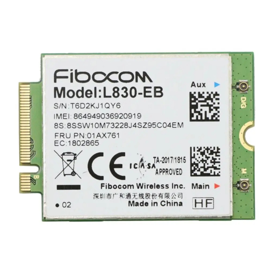
The product appearance for L830 module is shown in Figure 5-1: Figure 5-1 Module Appearance Dimension of Structure The structural dimension of the L830 module is shown in Figure 5-2: Reproduction forbidden without Fibocom Wireless Inc. written authorization - All Rights Reserved. L830-EB Hardware User Manual Page 35 of 39... -
Page 36: Interface Model
5.4 M.2 Connector The L830 module connects to AP via M.2 connector, it is recommended to use M.2 connector from Reproduction forbidden without Fibocom Wireless Inc. written authorization - All Rights Reserved. L830-EB Hardware User Manual Page 36 of 39... -
Page 37: Storage
American Electronic Component Industry Association (JEDEC). Please read the relevant application guidance and precautions referred to herein, to avoid the permanent Reproduction forbidden without Fibocom Wireless Inc. written authorization - All Rights Reserved. L830-EB Hardware User Manual... -
Page 38: Tray Package
The L830 module uses tray package, 20 pcs are packed in each tray, with 5 trays in each box and 6 boxes in each case. Tray packaging process is shown in Figure 5-4: Figure 5-4 Tray Packaging Process Reproduction forbidden without Fibocom Wireless Inc. written authorization - All Rights Reserved. L830-EB Hardware User Manual Page 38 of 39... -
Page 39: Tray Size
159.0± 0.3 20.0± 0.5 9.0± 0.5 24.5± 0.5 187.5± 0.2 ITEM 105.0± 0.2 9.0± 0.2 Figure 5-5 Tray Size (Unit: mm) Reproduction forbidden without Fibocom Wireless Inc. written authorization - All Rights Reserved. L830-EB Hardware User Manual Page 39 of 39...
Need help?
Do you have a question about the L830-EB and is the answer not in the manual?
Questions and answers