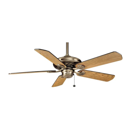
Casablanca Capistrano Indoor Ceiling Fan Owner's Manual
Casablanca indoor ceiling fan owners manual
Hide thumbs
Also See for Capistrano Indoor Ceiling Fan:
- Owner's manual (16 pages) ,
- Owner's manual (15 pages) ,
- Owner's manual and installation manual (2 pages)
Table of Contents
Advertisement
Quick Links
Advertisement
Table of Contents

Related Manuals for Casablanca Capistrano Indoor Ceiling Fan


Summary of Contents for Casablanca Capistrano Indoor Ceiling Fan
-
Page 2: Before You Start
• This fan is designed to be installed on an existing electrical outlet box. The outlet box must be UL Listed for ceiling fan installations, if it is not, a new box must be installed. Casablanca extension poles are available for sloped or high ceiling installations. -
Page 3: Sloped Ceiling Installations
MOUNTING RECOMMENDATIONS Before mounting your Casablanca fan, read the following helpful recommendations. The location of the fan, air circulation, and fan size are all important factors to consider before installation. Location Ceiling fans have practical uses in almost every room in your home. We suggest you follow these mount- ing recommendations as you decide where to install your Casablanca fan. -
Page 4: Preparation Instructions
PREPARATION INSTRUCTIONS Unpacking: Before assembling and installing your ceiling fan, remove all parts from the shipping cartons and check them against the parts listed here. Before discarding packaging material, be certain that all parts have been removed. LOCKING BOLT (MOTOR COUPLING) -
Page 5: Crossbar Mounting Bracket Installation
8-32 x 2 canopy screws and canopy lock washers. Tighten the screw firmly by hand only. Note: On sloped ceilings, align the canopy opening towards the top or room peak. CEILING FAN APPROVED OUTLET BOX CEILING WIRING CROSSBAR... -
Page 6: Canopy Electrical Connections
• WHITE wire from fan to white NEUTRAL wire in ceiling fixture outlet box. Secure with wire nut. • BLUE wire and BLACK power wire from fan to BLACK power wire in ceiling outlet box. Secure with wire nut. CANOPY HATCH INSTALLATION Step 5. - Page 7 APISTRANO Casablanca INSTALLING THE BLADE/BLADE HOLDER TO FAN MOTOR Step 8. To reach the blade holder mounting holes in the fan motor the dummy switch housing must be removed. Take out the two 5-32 X ” screws secur- ing the dummy switch housing and remove.
-
Page 8: Blade Installation
Step 10. Attach each blade to a blade holder securing it with the four blade screws provided. Using the screwdriver, tighten securely by hand only. Step 11. On the flywheel remove the five shipping blocks by unscrewing the screws. Set these screws aside for installing the blades in Step 12. -
Page 9: Completing Installation
Step 18! CONNECTING THE SWITCH HOUSING ASSEMBLY Step 14. Hold the switch housing up to the fan and connect the motor plug to the switch housing socket. The connec- tor is keyed to ensure correct installation. - Page 10 INSTALLING THE SWITCH HOUSING ASSEMBLY Step 15. Line up the two inner clear- ance holes in the cap with the two threaded holes in the switch mounting plate standoffs. CAUTION! Before continuing to the next step check that a wire or com- ponent inside the switch housing will not be pinched as it is installed.
- Page 11 HIGH speed setting. • No changes in household or fan wiring are required. • The fan may be turned ON and OFF by the W-4 wall control. CAUTION! Failure to set the pull-chain speed to HIGH can result in faulty operation of the fan and damage to the W-4/W-411 wall control.
-
Page 12: Speed Operation
CAUTION! Failure to set the pull-chain speed to HIGH can result in faulty operation of the fan and damage to the W-4/W-411 wall control. To confirm fan is set to HIGH: Turn W-4/W-411 fan speed switch to 'HI'—set fastest fan speed with pull chain. -
Page 13: Troubleshooting
Replace reverse switch assembly; replace PCB assembly; or replace motor unit. FAN WILL NOT OPERATE AT PROPER SPEEDS OR WILL NOT OPERATE AT ANY SPEED: Defective three-speed pull-chain switch assembly; or defective capacitor: Replace three-speed pull-chain switch assembly; or replace PCB assembly. - Page 14 7 6 1 C • P , C A 9 1 7 6 8 • 8 0 0 - 7 5 9 - F A N S ( 3 2 6 7 ) O R P O R A T E E N T E R R I V E O M O N A...
Need help?
Do you have a question about the Capistrano Indoor Ceiling Fan and is the answer not in the manual?
Questions and answers