Sign In
Upload
Download
Table of Contents
Contents
Add to my manuals
Delete from my manuals
Share
URL of this page:
HTML Link:
Bookmark this page
Add
Manual will be automatically added to "My Manuals"
Print this page
×
Bookmark added
×
Added to my manuals
Manuals
Brands
Clear-Com Manuals
Recording Equipment
ECLIPSE MATRIX
Instruction manual
Clear-Com ECLIPSE Instruction Manual
Dual channel party-line interface
Hide thumbs
Also See for ECLIPSE
:
Instruction manual
(89 pages)
,
User manual
(74 pages)
1
2
Table Of Contents
3
4
5
6
7
8
9
10
11
12
13
14
15
16
17
18
19
20
21
22
23
24
25
26
27
28
29
30
31
32
33
34
35
36
page
of
36
Go
/
36
Contents
Table of Contents
Bookmarks
Table of Contents
Table of Contents
Operation
Introduction
Description
Operation
Level Controls
Power LED
Send and Return Rejection Null Adjustment
Installation
Introduction
Installation in Interface Frame
Termination of Party-Lines
Wiring
Clear-Com Party Lines General Discussion
Two Separate Party Lines
Multiple Clear-Com Beltpack Channels from One Power Supply
To Connect "RTS" 2-Channel 2-Wire Party-Lines
Power from "Channel A" Line Only
Two Isolated RTS Lines
Adjustments
Power LED
Level Controls
Audio Rejection Null Adjustment
Configuration
Maintenance
Introduction
Bill of Materials
Diagrams
Specifications
Limited Warranty
Warranty Period
Technical Support
Warranty Repairs and Returns
Non-Warranty Repairs and Returns
Extended Warranty
Advertisement
Quick Links
Download this manual
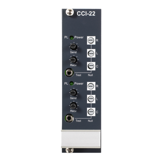
CLEAR-COM ECLIPSE
CCI-22
DUAL CHANNEL PARTY-LINE INTERFACE
INSTRUCTION MANUAL
Table of
Contents
Previous
Page
Next
Page
1
2
3
4
5
Advertisement
Table of Contents
Need help?
Do you have a question about the ECLIPSE and is the answer not in the manual?
Ask a question
Questions and answers
Related Manuals for Clear-Com ECLIPSE
Switch Clear-Com ECLIPSE MATRIX Instruction Manual
Matrix (89 pages)
Intercom System Clear-Com ECLIPSE DIGITAL WIRELESS User Manual
(74 pages)
Recording Equipment Clear-Com RS-100A Instruction And Service Manual
Clear-com rs-100a belt-pack station (6 pages)
Recording Equipment Clear-Com LQ Series Quick Start
(2 pages)
Recording Equipment Clear-Com Eclipse IFB-104 Instruction Manual
(29 pages)
Recording Equipment Clear-Com Eclipse 13.1 HX User Manual
(95 pages)
Recording Equipment Clear-Com Encore TW-47 Instruction Manual
Two-way radio interface; (30 pages)
Recording Equipment Clear-Com LQ Series Quick Start Manual
(2 pages)
Recording Equipment Clear-Com Encore IF4W4 Quick Start Manual
Partyline system 4-wire interface (2 pages)
Recording Equipment Clear-Com PL-PRO EF-1M Instruction Manual
4-wire and matrix direct interface (55 pages)
Recording Equipment Clear-Com FIM-108 Instruction Manual
Matrix fiber interface (25 pages)
Recording Equipment Clear-Com ECLIPSE AES-6 Instruction Manual
Digital interface (32 pages)
This manual is also suitable for:
Cci-22
Table of Contents
Print
Rename the bookmark
Delete bookmark?
Delete from my manuals?
Login
Sign In
OR
Sign in with Facebook
Sign in with Google
Upload manual
Upload from disk
Upload from URL


Need help?
Do you have a question about the ECLIPSE and is the answer not in the manual?
Questions and answers