Table of Contents
Advertisement
Quick Links
Advertisement
Table of Contents

Related Manuals for Clear-Com ECLIPSE AES-6


Summary of Contents for Clear-Com ECLIPSE AES-6
- Page 1 CLEAR-COM ECLIPSE AES-6 DIGITAL INTERFACE INSTRUCTION MANUAL...
- Page 2 Room 1806, Hua Bin Building No. 8 Yong An Dong Li Jian Guo Men Wai Ave Chao Yang District Beijing, P.R. China 100022 ® Clear-Com, CellCom/FreeSpeak and the Clear-Com Communications Systems logo are registered trademarks of The Vitec Group plc.
-
Page 3: Table Of Contents
CONTENTS OPERATION ......1-1 Introduction ..........1-1 Description . - Page 4 Vitec Group Communications AES-6 Digital Interface Instruction Manual...
- Page 5 IMPORTANT SAFETY INSTRUCTIONS 1. Read these instructions. 2. Keep these instructions. 3. Heed all warnings. 4. Follow all instructions. 5. Do not use this apparatus near water. 6. Clean only with dry cloth. 7. Do not block any ventilation openings. Install in accordance with the manufacturer’s instructions.
- Page 6 CAUTION RISK OF ELECTRIC SHOCK DO NOT OPEN This symbol alerts you to the presence of uninsulated dangerous voltage within the product's enclosure that might be of sufficient magnitude to constitute a risk of electric shock. Do not open the product's case. This symbol informs you that important operating and main- tenance instructions are included in the literature accompanying this product.
-
Page 7: Operation
OPERATION INTRODUCTION This chapter describes how to use the AES-6 Digital Interface. You can use this chapter once the Eclipse matrix system has been correctly installed and configured with the Eclipse Configuration System. To configure an Eclipse system with AES-6 interfaces Eclipse Configuration System (ECS) software V4.2 or later is required. -
Page 8: Operation
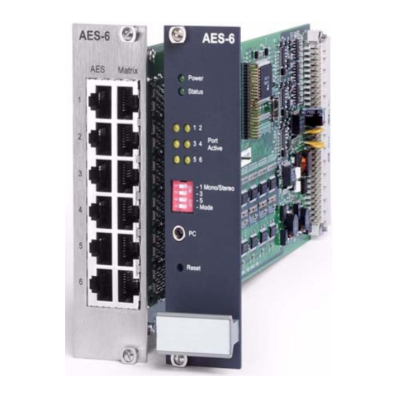
Figure 1-1: AES-6 Digital Interface Cards The AES-6 digital interface occupies one slot in an IMF-3 or IMF-102 interface module frame or a Median matrix. Connections to the Eclipse matrix are via 8-pin RJ-45 connectors on the rear panel. Connections to the panel may either be via RJ-45 and CAT5 cable or BNC and coax cable depending on the rear card fitted. -
Page 9: Power Led
Figure 1-2: AES-6 Front Interface Card POWER LED The green power indicator LED lights when DC power is supplied to the interface. The interface is powered by the interface rack or Median matrix. STATUS LED The green status LED indicates CPU activity on the card. This LED will indicate if the card CPU is functioning correctly. - Page 10 CPU STATUS LED STATE MEANING Card software failed to boot Slow flash (approx 1Hz) 50:50 Software is running OK Quick blink flash (approx 1Hz ) FPGA image download in progress 25:75 Software has detected a hardware Fast flash (approx 5Hz) 50:50 failure.
-
Page 11: Panel Connectivity
CPU LED CODE LED 1 LED 2 LED 3 LED 4 LED 5 LED 6 MEANING Flash Flash RAM test fail Flash Flash Corrupt Code Image FPGA Flash Erase Flash Flash Flash Fail Flash Flash FPGA Load Fail Flash Flash Flash FPGA Test Fail Flash... -
Page 12: Port Configuration Switches
AES-6 interface (Figure 1-2). Three of the DIP switches configure the rear card ports between mono and stereo modes. The fourth DIP switch (Mode) is used to configure the card for either Clear-Com panels (OFF) or third party equipment (ON). -
Page 13: Data Port
Figure 1-3: AES-6 DIP Switch Settings for Clear-Com Panels Figure 1-4: AES-6 DIP Switch Settings for Third Party Equipment DATA PORT The data port is a 3.5mm jack socket allowing the AES-6 to be connected to a PC for software/diagnostics download. To connect to a PC a PD4007 download cable is required. - Page 14 1 - 8 Vitec Group Communications AES-6 Digital Interface Instruction Manual...
-
Page 15: Installation
INSTALLATION INTRODUCTION This chapter describes the installation of the AES-6 digital interface, including setting DIP switches and wiring to external devices. INSTALLATION IN INTERFACE FRAME To install the AES-6 digital interface module in the IMF-3 or IMF-102 interface frame or Eclipse Median: 1. - Page 16 • 4222E The V-Series panel types supported by this card are: • V12LD • V12PD • V24LD • V24PD • V12LDD This card is for use with installation where the data connections to the 4000 Series II and V-Series panels or third party equipment are made using coaxial cable rather than CAT5 cable.
-
Page 17: Aes-6-Rj Interface Card
‘ON’ position. An example of the type of panel that could be used with the AES-6-CX card in either mono or stereo mode is the Clear-Com 4222E panel. AES-6-RJ INTERFACE CARD The AES-6-RJ rear card has six pairs of RJ-45 ports allowing 4000 Series II panels, V-Series panels with an AES-3 interface and third party equipment to be connected using CAT5 cable. -
Page 18: Mono Configuration
Mono Configuration Figure 2-7: AES-6-RJ Connected for Mono Panels For AES-6-RJ connected panels standard straight through CAT5 cable may be used to connect panels to the AES-6 interface and the AES-6 interface to the matrix. 2 - 4 Vitec Group Communications AES-6 Digital Interface Instruction Manual... -
Page 19: Stereo Configuration
Figure 2-8: AES-6-RJ Connected for Mono Third Party Equipment When a matrix port is connected to an AES-6 interface for audio only operation the matrix port should be configured as “AES Mono” in ECS (Setup Matrix Hardware). Stereo Configuration For stereo use i.e. separate left and right ear audio streams only half the RJ45 ports can be used with the sources being connected to alternate ports. - Page 20 Figure 2-9: AES-6-RJ Connected for Stereo Panels When operating in stereo mode the matrix will send two audio streams to the panel consisting on the main intercom audio and auxiliary audio. The panel will return the panel microphone audio to the matrix. Figure 2-10: Stereo Audio Flow in AES-6 Systems When configuring V-Series panels for stereo mode in ECS the Audio Mixer should be set to “Layout Binaural coax/AES”...
- Page 21 Figure 2-11: AES-6-RJ Connected for Stereo Third Party Equipment V-Series panels with AES-3 option cards can also be connected to an AES-6 interface via an AES-3 compliant network. Figure 2-12: AES-3 Networking The V-Series panel ES-3 option card uses a data format of 24-bit audio data and 8-bit user control data.
-
Page 22: Cable Pinouts
CABLE PINOUTS The CAT5 cables used to connect either type of AES-6 rear card (AES-6-CX and AES-6-RJ) to a matrix use the following pinout. PIN NUMBER WIRE COLOR FUNCTION White/Orange Data Transmit (Tx+) Orange Data Transmit (Tx-) White/Green Audio Output (+) Blue Audio Input (+) White/Blue... - Page 23 Standard straight-through CAT5 cables may be used for this purpose. Up to 200m of cable run between the panel or AES source and the AES-6-RJ interface or between the AES-6 interface and the matrix at a 48K sample rate is possible using 24AWG cable. If 26AWG cable is used the maximum cable run will be less than 200m.
- Page 24 2 - 1 0 Vitec Group Communications AES-6 Digital Interface Instruction Manual...
-
Page 25: Maintenance
MAINTENANCE The AES-6 functional block diagram is shown below. Figure 3-1: AES-6 Functional Block Diagram Vitec Group Communications 3 - 1 AES-6 Digital Interface Instruction Manual... - Page 26 3 - 2 Vitec Group Communications AES-6 Digital Interface Instruction Manual...
-
Page 27: Specifications
Humidity 40 - 90% non-condensing Notice About Specifications While Clear-Com makes every attempt to maintain the accuracy of the information contained in its product manuals, that information is subject to change without notice. Performance specifications included in this manual are design-center specifications and are included for customer guidance and to facilitate system installation. - Page 28 4 - 2 Vitec Group Communications AES-6 Digital Interface Instruction Manual...
-
Page 29: Limited Warranty
• UHF wireless intercom systems have a limited warranty of three years. • All other Clear-Com and Drake brand systems and products, including beltpacks, have a limited warranty of two years. The warranty starts at the time of the product’s original purchase. The... -
Page 30: Warranty Repairs And Returns
Telephone for Europe, Middle East and Africa: +49 40 6688 4040 or +44 1223 815000 Telephone for the Americas and Asia: +1 510 337 6600 Email: vitec.support@AVC.de Once the standard warranty period has expired, the User Support Center will continue to provide telephone support if you have purchased an Extended Warranty. -
Page 31: Extended Warranty
EXTENDED WARRANTY You can purchase an extended warranty at the time of purchase or at any time during the first two years of ownership of the product. The purchase of an extended warranty extends to five years the warranty of any product offered with a standard two-year warranty. The total warranty period will not extend beyond five years. - Page 32 This limited warranty is not transferable and cannot be enforced by anyone other than the original consumer purchaser. This warranty gives you specific legal rights and you may have other rights which vary from country to country. Vitec Group Communications Warranty...
Need help?
Do you have a question about the ECLIPSE AES-6 and is the answer not in the manual?
Questions and answers