
Related Manuals for Clear-Com Eclipse 13.1 HX


Summary of Contents for Clear-Com Eclipse 13.1 HX
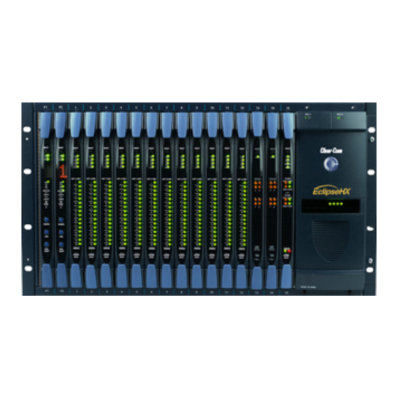
- Page 1 User Guide Eclipse 13.1 HX Installation Guide Part Number: PUB-00229 Revision A Date: September 18, 2023...
-
Page 2: Table Of Contents
User Guide | FreeSpeak Edge Table of contents 1 Important Safety Instructions 2 Installation Overview 2.1 Before Installing the System 2.2 Installing the Eclipse HX System 2.3 After Installing the Eclipse HX System 3 Locating System Components 3.1 Locating Eclipse HX Matrices 3.2 Locating Interface Frame(s) and Power Supplies 3.3 Locating User Panels 3.4 Locating the External Computer for EHX... - Page 3 User Guide | FreeSpeak Edge 6.3 Tie-Line (Audio Only) Linking 6.4 E1 / T1 Linking 6.5 Fiber-Optic Linking 7 Glossary 8 Limited Warranty 8.1 Warranty Period 8.2 Technical Support 8.3 Warranty Repairs and Returns 8.4 Non-Warranty Repairs and Returns 8.5 Extended Warranty 8.6 Service Contract 8.7 Liability Page 3...
- Page 4 The product described in this document is distributed under licenses restricting its use, copying, distribution, and decompilation / reverse engineering. No part of this document may be reproduced in any form by any means without prior written authorization of Clear-Com, an HME Company.
-
Page 5: Important Safety Instructions
User Guide | FreeSpeak Edge Important Safety Instructions 1. Read these instructions. 2. Keep these instructions. 3. Heed all warnings. 4. Follow all instructions. 5. Do not use this apparatus near water. 6. Clean only with dry cloth. 7. Do not block any ventilation openings. Install in accordance with the manufacturer’s instructions. - Page 6 User Guide | FreeSpeak Edge EMC AND SAFETY This Product's power supply meets all relevant CE, FCC, UL, and CSA specifications set out below: EN55103-1 Electromagnetic compatibility. Product family standard for audio, video, audio-visual, and entertainment lighting control apparatus for professional use. Part 1: Emissions.
-
Page 7: Installation Overview
Save all packing materials (boxes, Styrofoam). If any item has been shipped in error, is malfunctioning, or requires warranty service, use the original packing materials to return that item to Clear-Com. 2.1.2 Select Locations for the System Components Select locations for the Eclipse HX matrix, interface cards, interface modules, user panels, PC, and any other system components. - Page 8 User Guide | FreeSpeak Edge The Eclipse HX matrix is the central connecting point of the system. All other devices are connected, either directly or indirectly, to the matrix, and this central role must be accounted for in your system topography. Note: For additional information about locating the Eclipse HX matrix system, see Locating...
- Page 9 USB connectors, adapters are available from computer parts suppliers. However, you will be required to install drivers for USB-to-serial port connections. Important note: Because of compatibility issues with some products, Clear-Com does not recommend the use of USB- to-serial port connections. Page 9...
- Page 10 User Guide | FreeSpeak Edge System component Connections User panels (V- An analog connection, using shielded CAT5 4-twisted pair Series, I-Series user cables with RJ-45 connectors, is the most common way of panels and 2X10 connecting V-Series user panels and I-Series panels to the Touch Desktop matrix.
- Page 11 User Guide | FreeSpeak Edge System component Connections Interface modules Interface modules are connected to the matrix using: Particular wiring schemes (for each module type) on the DB-9 connectors on the rear of the associated interface frame (IMF-3). Shielded CAT5 4-twisted pair cables with RJ-45 connectors.
-
Page 12: Installing The Eclipse Hx System
Installing the Matrix in a 19” Rack Install the matrix in a standard Electronics Industry Association 19-inch wide (48.26 cm) equipment rack. Clear-Com recommends installing the matrix to the center portion of the rack, allowing easy access to the connectors on the rear of the matrix. - Page 13 Install the intercom cables between the Eclipse HX matrix and the other system components (user panels and interface frames). Clear-Com recommends that you route cables before wiring the connectors to the cables. Note: For more information about routing cables, see Locating System Components.
- Page 14 User Guide | FreeSpeak Edge Each component of the Eclipse HX system requires AC power except for the IMF-3 and some interface modules. The IMF-3 requires an external power supply. The XP-type expansion panels receive power from the panels to which they are connected. If you are installing an IMF-3, install the DC power cables that connect the power supply to the matrix.
-
Page 15: After Installing The Eclipse Hx System
User Guide | FreeSpeak Edge Only connect power supply to earthed supply sockets. Ensure that the power supply is routed to avoid sharp bends, hot surfaces, pinches and abrasion. Refer all servicing to qualified service personnel. For more safety guidance, see the Safety Instructions supplied with this product. - Page 16 User Guide | FreeSpeak Edge Specification Description / Value Memory 1GB RAM Hard disk 1GB minimum 32 bit, 2GB minimum 64 bit. Input devices CD-ROM drive Display resolution SVGA User entry Keyboard, Mouse Ports 2 serial ports and/or network IEEE 802.3 Ethernet card Network IEEE 802.3 Ethernet card Operating systems...
- Page 17 User Guide | FreeSpeak Edge Specification Description / Value Operating systems EHX 8.5.1 runs on the following versions of Windows: Microsoft Windows 7 (32-bit and 64-bit). Microsoft Windows 8.1 (32-bit and 64-bit). Microsoft Windows 10 (32-bit and 64-bit). Microsoft Windows Server 2008 R2 (64-bit). Microsoft Windows Server 2012 R2 (64-bit).
- Page 18 User Guide | FreeSpeak Edge Page 18...
- Page 19 User Guide | FreeSpeak Edge Note: For more information about the lights and controls on the CPU card, see either. The Eclipse HX-Omega User Guide. The Eclipse HX-Median User Guide. The Eclipse HX-Delta User Guide Eclipse HX-PiCo The LEDs on the front of the matrix indicate its operational status: Note: For more information about the lights and controls on the front of the Eclipse HX-PiCo, see the Eclipse HX-PiCo User Guide.
-
Page 20: Locating System Components
User Guide | FreeSpeak Edge Locating System Components This section provides help with deploying (locating and arranging) the principal components of your Eclipse HX system, including: Eclipse HX matrices (Eclipse HX-Omega, Eclipse HX-Median, Eclipse HX-Delta and Eclipse HX-PiCo). An external computer (for the EHX configuration software). Interface frame(s) (the IMF-3 and IMF-102), which host interface modules. - Page 21 User Guide | FreeSpeak Edge forced air cooling. The primary fan runs continuously. If the temperature in the matrix exceeds a set threshold and extra cooling is required, a secondary fan switches on to increase the air flow in the matrix. The fan-on alarm LED on the front of the alarm module illuminates red to indicate that the secondary fan is on.
-
Page 22: Locating Interface Frame(S) And Power Supplies
8 interface modules. The 3RU Eclipse HX-Delta matrix has 4 slots for circuit cards, and slots for up to 3 interface modules. Clear-Com also offers two types of interface frame to host interface modules. 3.2.1... - Page 23 User Guide | FreeSpeak Edge The IMF-3 frame has a rear panel for each interface module. The layout of the rear panel is the same for most interface modules. However, the use of the rear panel connectors varies according to the type of interface. To enable easy access to indicators (lights) and controls, locate the interface frame(s) in a convenient location.
-
Page 24: Locating User Panels
User Guide | FreeSpeak Edge Locating User Panels Locate all user panels (V-Series, I-Series and 2X10 Touch Desktop panels) at comfortable heights for operation. To allow for cable connectors, leave at least 2 inches (50.8 mm) of clearance behind the panel chassis. Adjust the brightness of the display to suit your requirements. - Page 25 However, you will be required to install drivers for USB-to-serial port connections. Because of differences in PC hardware, operating systems and USB-to-serial converters, Clear-Com cannot provide a recommendation for a specific USB-to-serial converter. Page 25...
-
Page 26: Powering System Components
User Guide | FreeSpeak Edge Powering System Components This section provides guidance for providing power to the following components of the Eclipse HX system: Eclipse HX matrices (Eclipse HX-Omega, Eclipse HX-Median, Eclipse HX-Delta and Eclipse HX-PiCo). Interface frame(s) (the IMF-3 and IMF-102), which host interface modules. User panels (V-Series, I-Series and 2X10 Touch Desktop panels). -
Page 27: Powering User Panels
User Guide | FreeSpeak Edge A fully equipped Eclipse HX-Omega or HX-Median matrix requires 100 - 240 VAC at 50 - 60 Hz with a maximum dissipation of 300 W. 4.1.2 Eclipse HX-Delta The Eclipse HX-Delta's power is provided by two external 12V power supply units (for redundancy). -
Page 28: Powering Interface Frames
User Guide | FreeSpeak Edge 4.2.2 2X10 Touch Desktop panel) The 2X10 Touch Desktop panel has a 2.5mm Power jack connector with screwlock retention to accept the required input power of 12VDC, 2A. An AC/DC Desk Top Power Adapter is supplied with the unit. The power adapter has the following specification: Input connector : IEC-320 C14 male receptacle Input AC Voltage range : 100-240VAC... - Page 29 An audible alarm is included in the PSU-101, and an additional set of alarm-relay contacts are provided on the supply. Clear-Com recommends that these contacts be connected to the external alarm input of the matrices. If any of the power supplies in the PSU-101 fails, a system alarm is activated. LEDs on the front of the PSU-101s indicate the failure.
- Page 30 User Guide | FreeSpeak Edge Note: For more information about the IMF-3, see the IMF-3 Manual. 4.3.2 IMF-102 The IMF-102 has an internal power supply and a rear panel connector for connecting redundant power. The power supply is universal, operating over a voltage range of 90 - 250 VAC. The maximum dissipation is 20W.
-
Page 31: Wiring System Components
Interface frames and interface modules. External alarms. Four-wire audio devices. Analog partyline systems (including Clear-Com Encore). It also includes guidance on using GPIs / GPOs to trigger actions, and procedures for enabling E & M signaling. Most user panels and interfaces connect to a matrix using CAT5 single 4-pair shielded RJ-45 terminated cables. - Page 32 The use of shielded cables throughout the installation for EMC conformance. Unshielded cables can be used but in this case Clear-Com does not guarantee the crosstalk and noise figures.
- Page 33 User Guide | FreeSpeak Edge The following products are recommended as possible sources for cables, connectors and tools: Product type Recommended product(s) Crimper Siemon PT908 or AMP 2-231652-1 with 853400-1 dies Stripper Siemon CPT Tester Siemon STM-8 Connector RJ-45 Shielded 26-22 Siemon PS-8-8 AWG Stranded or Solid RJ-45 Cinch...
-
Page 34: Connecting The Matrix To A Pc Running Ehx
User Guide | FreeSpeak Edge 3. In the correct color sequence, pull one wire at a time, straight out, clamping it in place between your thumb and forefinger. If a wire must cross the others, ensure that this occurs inside the jacket. Ensure that your color sequence matches the other side and it does not reverse. - Page 35 User Guide | FreeSpeak Edge Ethernet connection allows single or multiple PCs to control, configure, monitor, and diagnose single or multiple matrices from anywhere on the WAN / LAN (see also the Connecting the matrix to an Ethernet network section. For Eclipse HX-Omega, Eclipse HX-Median and Eclipse HX-PiCo, a ferrite core must be added to the socket end of each Ethernet cable to comply with European EMC standards.
- Page 36 User Guide | FreeSpeak Edge Eclipse HX-PiCo A DB-9F connector is used at the PC, when wiring for an Eclipse HX-PiCo serial connection. The 3.5mm jack socket is labeled RS-232 on the front of an Eclipse HX-PiCo. Ensure that: The data connections of Pin 2 to jack plug tip and Pin 3 to jack plug ring are followed. Pin 5 (DB-9F) goes through to the jack plug screen.
-
Page 37: Connecting The Matrix To An Ethernet Network
User Guide | FreeSpeak Edge PC Connection Eclipse HX-PiCo (3.5mm jack) (DB-9F) Pin 1 Links to Pins 4,6,8 on PC side Pin 2 Pin 3 Ring Pin 4 Links to 1, 6, 8 on PC side Pin 5 Screen Pin 6 Links to Pins 1, 4, 8 on PC side Pin 7 Pin 8... -
Page 38: Connecting The Matrix To A Pc Running Dynam-Ec
Connecting the Matrix to a PC Running Dynam-EC Dynam-EC is the is a multi-user, multi-matrix PC based software package which provides fast, intuitive audio routing control for Eclipse HX systems. Note: For more information, see the product description on the Clear-Com website. 5.4.1 LMC-64 Interface Card Access to the audio level metering functionality of Dynam-EC is usually achieved using the LMC-64 interface card. -
Page 39: Connecting The Matrix To User Panels
User Guide | FreeSpeak Edge For more information about the LMC-64 interface card (which you can fit to either an Eclipse HX-Omega, Eclipse HX-Median or Eclipse HX-Delta matrix), see the: LMC-64 Manual Eclipse HX-Omega User Guide Eclipse HX-Median User Guide Eclipse HX-Delta User Guide Connecting the Matrix to User Panels The Eclipse HX system uses a 4-pair (analog) wiring scheme between the matrix and user... -
Page 40: General Purpose Outputs (Gpos)
User Guide | FreeSpeak Edge General Purpose Outputs (GPOs) A general purpose output (GPO) or relay is a switch that is controlled remotely. The relay is programmed in EHX to close a contact whenever a user panel’s key is pressed. When the Page 40... - Page 41 User Guide | FreeSpeak Edge contact is closed, it completes an electronic circuit’s signal path so that a remote device (such as a light) is powered. A GPO can be programmed to mute a speaker, to turn on an applause light, open a door lock, or perform a variety of other functions.
- Page 42 User Guide | FreeSpeak Edge DB-25M Connector Pin 7 Common RELAY3 Pin 8 Normally closed Pin 9 Normally open Pin 10 Common RELAY4 Pin 11 Normally closed Pin 12 Normally open Pin 13 Digital ground Pin 14 Common RELAY5 Pin 15 Normally closed Pin 16 Normally open...
-
Page 43: General Purpose Inputs (Gpis)
User Guide | FreeSpeak Edge Note The general purpose outputs are single-pole double-throw relays with contact ratings of 30 VDC (volts direct current) at 1 ampere. General Purpose Inputs (GPIs) You can connect an external logic device (such as an external foot switch, a panel-mounted switch, or the logic output of some other device) to the connector labeled GP IN on the rear of the Eclipse HX matrix. - Page 44 User Guide | FreeSpeak Edge When the external logic device is activated, it sends a control signal into the matrix to perform one of several preset functions, such as turning an intercom panel’s microphone on or off, muting a microphone’s output, or turning a panel’s speaker off. The function to perform and the panel upon which it is performed is configured using the Eclipse configuration software (EHX).
- Page 45 User Guide | FreeSpeak Edge DB-25F Connector Pin 20 N / A Pin 21 N / A Pin 22 V IN + Pin 23 V IN + Pin 24 V IN - Pin 25 V IN - Page 45...
- Page 46 User Guide | FreeSpeak Edge 5.7.1 Modes for General Purpose Inputs (GPIs) General-purpose inputs (GPIs) operate in either of two modes: Opto-isolated mode, which requires the externally connected equipment to provide the current to power the general-purpose input. Page 46...
- Page 47 User Guide | FreeSpeak Edge Non-isolated mode, which means that the externally connected equipment is not required to power the general-purpose input. A voltage output on the GP IN connector supplies the current. To select a mode, move the J1 jumper on the CPU rear card to one of two positions (The J1 jumper is located on the inner-frame side of the DB-25 connector): 1.
-
Page 48: E & M Signalling With An E-Que E1 / T1 Interface Card
User Guide | FreeSpeak Edge To cause an input to detect an active signal, current must flow from the relevant input pin. The external device should draw no current to cause an inactive input and at least 5 mA to cause an active input. - Page 49 User Guide | FreeSpeak Edge 5.8.1 Example: Ship-to-Shore Satellite System In the image above, E & M signaling is carried with audio channels on the direct T1 connection and then split into logic functions in the matrix: 1. The direct E1 / T1 connection carries audio and E & M signaling (the incoming E & M signal from the on-shore communications system.
- Page 50 (T1 direct = ports 25 – 48 / E1 direct = ports 31– 60) correspond to the two physical T1 / E1 connections with the E-QUE card Recommendation: For T1 direct E-QUE cards, Clear-Com recommends that you select the G711 µ-law codec for optimum audio quality.
- Page 51 User Guide | FreeSpeak Edge 8. In Card Properties > E & M Signaling, select Enable E & M Signaling [ Click OK. Top Half (T1 direct = ports 1 – 24 / E1 direct = ports 1 – 30) and Bottom Half (T1 direct = ports 25 –...
-
Page 52: Connecting The Matrix To An External Alarm
User Guide | FreeSpeak Edge d. Label the second control REC1. e. Add the Radio In route to REC1. f. Add the E & M relay / GPO (the relay associated with the first configured port on the E1 / T1 direct E-QUE card) to REC1. Note: This relay receives the E &... - Page 53 User Guide | FreeSpeak Edge Note The relay contacts connected to pins 4, 5 and 9 are ‘dry’, and are rated at 1 A at 24 VDC. They are not recommended for AC mains line current. Pins are provided for adding an additional alarm source to the matrix’s alarm system. Pin 6 is an alarm input to the matrix.
-
Page 54: Connecting To A Four-Wire Audio Device
User Guide | FreeSpeak Edge 5.10 Connecting to a Four-Wire Audio Device An external four-wire audio device can be directly connected to a port connector through the four audio pins. If there is excessive noise on the lines between the device and the matrix, the device may be electronically unbalanced with the rest of the system. - Page 55 User Guide | FreeSpeak Edge Clear-Com also offers two types of interface frames, to house interface modules, the IMF-3, and the IMF-102 interface frames. For more information, see Locating Interface Frame(s) and Power Supplies. The following figure shows the pin assignments of RJ-45 connectors when used to connect to...
- Page 56 User Guide | FreeSpeak Edge Pinout of DB-9M I/O connector for FOR-22 Connector Description Pin 1 and Pin 6 = Audio output Pin 2 and Pin 7 = Audio input Pin 3 and Pin 8 = Logic input (+ / - 4 to 50V) Pin 4 = Relay normally closed Pin 9 = Relay wiper Pin 5 = Relay normally open...
- Page 57 User Guide | FreeSpeak Edge A FOR-22 interface connects to an Eclipse HX matrix through the two RJ-45 connectors on its rear panel. The top RJ-45 is for the first channel of the interface module. The lower RJ-45 is for the second channel.
- Page 58 Bring both channels out either DB connector together to create a TW-type partyline connection. DB-9M interface I/O connector for CCI-22 Connector Description Channel #1: Pin 1 = Clear-Com / RTS Pin 2 = Ground Pin 3 = +30 VDC Power Pin 4 = Audio Page 58...
- Page 59 Pin 8 = + 30 VDC Power Pin 9 = Audio Stations on Clear-Com analog partyline systems (such as Encore) connect to each other with two-conductor shielded microphone cable. One conductor carries the DC power (28 to 30 V) for that channel, while the other conductor carries the duplex two-way intercom audio signal plus DC Call Light signaling for that channel.
- Page 60 User Guide | FreeSpeak Edge Enable telephone calls directly to or from any intercom panel in an Eclipse system. The TEL-14 uses each of the RJ-45 connectors on its rear panel for connection to a matrix port. One RJ-45 is for Line A of the interface and the other RJ-45 is for Line B of the interface. The DB-9M connectors are the Line A and Line B connections to the telephone line.
- Page 61 User Guide | FreeSpeak Edge Page 61...
- Page 62 The lower RJ-45 connector is used to connect telephone line B to the matrix. Note: To allow use of a common RJ-11 terminated telephone line, Clear-Com provides two DB-9F to RJ-11 adapters (Clear-Com part 770025). For internal dip-switch settings and adjustments, see the TEL-14 Manual.
- Page 63 DB-9M connector. Connects to the second telephone line, line RJ-45 connector. Connects telephone line B to the matrix. Note: To allow use of a common RJ-11 terminated telephone line, Clear-Com provides two DB-9F to RJ-11 adapters (Clear-Com part 770025) For internal dip-switch settings and adjustments, see the TEL-14 Manual.
- Page 64 User Guide | FreeSpeak Edge Use the RJ-11 to DB-9F adapters supplied by Clear-Com with the TEL-14 interface module. Directly wire each telephone line to a DB-9F connector using the pinouts as shown in the following figure (which displays the wiring diagram of the RJ-11 to DB-9F adapter).
- Page 65 User Guide | FreeSpeak Edge These contacts are not connected to any other circuitry inside the interface, and can be used to energize a line-in-use indicator light on a standard multiline phone set, or for any other low- power application. 5.11.4 Wiring Scheme for the RLY-6 Interface Module The RLY-6 interface module provides six fully programmable SPDT (single pole, double throw)
- Page 66 User Guide | FreeSpeak Edge Note: If both GPI-6 and RLY-6 interfaces are used the GPI-6 interfaces must be placed first in the daisy chain Page 66...
- Page 67 User Guide | FreeSpeak Edge Wiring external devices to an RLY-6 interface module To connect external devices to an RLY-6 interface module, use the two DB-9M connectors on the rear cable assembly panel for the interface module. If a DB-9F is plugged into the connector labeled CH. A I/O, relays 1 to 3 are available on that connector.
- Page 68 User Guide | FreeSpeak Edge RLY-6 DB-9M connector pinout #1/4 Normally open #2/5 COM #3/6 Normally closed #3/6 Normally open #1/4 COM #2/5 Normally closed #2/5 Normally open Page 68...
- Page 69 User Guide | FreeSpeak Edge RLY-6 DB-9M connector pinout #3/6 COM Wiring the RLY-6 to an IMF-102 interface frame The wiring of an RLY-6 interface that is placed in an IMF-102 interface frame is the same as the wiring for a RLY-6 interface placed in an IMF-3 interface frame (see the Wiring the RLY-6 to an IMF-3 interface frame image.
- Page 70 User Guide | FreeSpeak Edge 1. Connect one end of a short RJ-45 cable into the lower RJ-45 (CH. B MATRIX) for the first GPI-6. 2. Connect the other end of the cable into the top RJ-45 (CH. A MATRIX) connector for the additional GPI-6.
- Page 71 User Guide | FreeSpeak Edge GPI-6 DB-9M connector pinout Connector Description #1/4 Input A #2/5 Input A Page 71...
- Page 72 User Guide | FreeSpeak Edge GPI-6 DB-9M connector pinout #3/6 Input A Ground Ground #1/4 Input B #2/5 Input B #3/6 Input B Power source Page 72...
- Page 73 User Guide | FreeSpeak Edge The image above shows you how to connect switches or contacts using the power source provided by the GPI-6 module or powering switches from external sources. Each input can be wired to be isolated from each other as a further variation. Wiring the GPI-6 to an IMF-102 interface frame The wiring of a GPI-6 interface that is placed in an IMF-102 interface frame is the same as the wiring for a GPI-6 interface placed in an IMF-3 interface frame.
-
Page 74: Connecting Matrices
User Guide | FreeSpeak Edge Connecting Matrices You can connect your Eclipse HX matrices together, to expand the geographical range or the port density of a system. You can connect: Up to 64 Eclipse HX matrices (Eclipse HX-Omega, Eclipse HX-Median, Eclipse HX-Delta and Eclipse HX-PiCo) using trunk lines and an Ethernet network. - Page 75 User Guide | FreeSpeak Edge You can connect a dedicated audio trunk line using: The receive lines of an MVX-A16 serial port on one matrix and the appropriate send lines of an MVX-A16 serial port on the second matrix. An E-QUE interface module, or an E-FIB (Fiber) card and fiber optic cables. Note Only Eclipse HX-Median, Eclipse HX-Omega and Eclipse HX-Delta matrices can be connected using E-QUE / E-FIB cards and fiber optic cables.
- Page 76 User Guide | FreeSpeak Edge Note: Also applies to the E-32 matrix, the immediate predecessor of the Eclipse HX-PiCo. The connectors have standard Ethernet pin assignments (see the images and table below). Page 76...
- Page 77 User Guide | FreeSpeak Edge Description Pin 1 Transmit data + Pin 2 Transmit data - Pin 3 Receive data + Pin 4 Unused Pin 5 Unused Page 77...
-
Page 78: Linking Eclipse Hx-Pico Matrices With The Pico-Link
User Guide | FreeSpeak Edge Description Pin 6 Receive data - Pin 7 Unused Pin 8 Unused Linking Eclipse HX-Pico Matrices with the PiCo-Link You can create one non-blocking 64 port Eclipse HX system by connecting two Eclipse HX- PiCo matrices together, using the PiCo-Link RJ-45 connectors on the matrices. This type of connection gives each connected matrix access to all of the audio ports of both matrices without using up ports for trunk lines (although logical routing such as IFBs, Telephone handling and ISOs cannot be used across the matrices). -
Page 79: Tie-Line (Audio Only) Linking
Notes: You can also use the E-QUE card for E & M signaling. For more information, see Signalling with an E-QUE E1 / T1 Interface Card. For more information about the E-QUE interface card, and other Clear-Com interface cards, see either: The Eclipse HX-Omega User Guide. - Page 80 User Guide | FreeSpeak Edge E1 120 Ohm Transmit Pulse Amplitude. Balanced. 120 Ohm Line Impedance. No Signaling. G.722 64 kbit/s Audio Encoding. Tx Clock locally generated. Rx Clock Line Recovered. The following image shows Matrix to Matrix direct E1 Trunking, using a direct connection between the matrices using a CAT5 crossover cable.
- Page 81 User Guide | FreeSpeak Edge For EI Trunking with an E1 Network, E1 ports 1 and 5 of the E-QUE interface are connected using standard straight-through CAT5 cables rather than crossover CAT5 cables. The E-QUE interface can also be used to connect the matrix to third party equipment using E1 port 1 or 5.
- Page 82 User Guide | FreeSpeak Edge The CAT5 cable connecting the E1 port on the E-QUE rear card may be a crossover cable or a straight-through cable depending on the requirements of the third-party equipment. The E-Que interface should be set to Direct in EHX. 6.4.2 T1 Trunking The E-QUE interface card can provide T1 trunking between Eclipse HX systems and between...
- Page 83 User Guide | FreeSpeak Edge Balanced. 120 Ohm Line Impedance. No Signaling. G.722 64 kbit/s Audio Encoding. Tx Clock locally generated. Rx Clock Line Recovered. T1 trunking between matrices can also be achieved over a E1 network as shown in the image below.
-
Page 84: Fiber-Optic Linking
The E-FIB interface card is the fiber-net interface for the Eclipse HX-Omega, Eclipse HX- Median and Eclipse HX-Delta matrices. The card is supplied with main and backup fiber rings. Note For more information about the E-FIB interface card, and other Clear-Com interface cards, see the: Eclipse HX-Omega User Guide... - Page 85 User Guide | FreeSpeak Edge A front card with status indicators. A rear card with two Duplex LC terminated fiber optic connectors (TXVRA and TXVRB). E-FIB cards use 9/125µ single mode fiber optic cables. On the rear card, the TX1/RX1 connector is used for the main ring and the TX2/RX2 connector is used for the secondary ring.
- Page 86 User Guide | FreeSpeak Edge Page 86...
-
Page 87: Glossary
User Guide | FreeSpeak Edge Glossary GlossaryTerm Definition Agent IC Mobile client for iOS that gives remote panel functionality. Any of the Eclipse HX matrix’s analog input/output RJ-45 connectors that are used to connect cable from the matrix Analog Port to panels and interfaces. - Page 88 User Guide | FreeSpeak Edge GlossaryTerm Definition Central matrix The term central matrix is used to differentiate the central hardware and software of the intercom system from the connected audio devices. The central matrix consists of: The metal housing for the circuit cards and power supplies.
- Page 89 User Guide | FreeSpeak Edge GlossaryTerm Definition FreeSpeak II™ Digital wireless communications product. Full duplex Refers to transmission of signals in two directions simultaneously. Hopping Refers to making a trunk connection through other matrices to a destination matrix. Interruptible Foldback. The term foldback refers to sending program audio / feed, or some other audio mix, back to announcers while they are on the air.
- Page 90 User Guide | FreeSpeak Edge GlossaryTerm Definition The ISO function, short for panel ISOlation, allows a panel operator to call a destination and interrupt all of that destination’s other audio paths and establish a private conversation. When the call is completed the destination’s audio pathways are restored to their original state before the interruption.
- Page 91 User Guide | FreeSpeak Edge GlossaryTerm Definition Partyline A wired shared communication system based on a single screened pair of wires. See the Encore range. Matrix requires the CCI-22 to interface to it. Port Any of the input/output connections (RJ-45 connectors) on the back panel of the central matrix.
-
Page 92: Limited Warranty
Clear-Com in its discretion deem it necessary, replacing the product in accordance with this limited warranty. In no event will Clear-Com be responsible for incidental, consequential, or special loss or damage, however caused. -
Page 93: Warranty Repairs And Returns
User Guide | FreeSpeak Edge Instructions for reaching Clear-Com’s User Support Centers are given below. Americas and Asia-Pacific Headquarters California, United States Tel: +1.510.337.6600 Email: CustomerServicesUS@clearcom.com Europe, Middle East, and Africa Headquarters Cambridge, United Kingdom Tel: +44 1223 815000 Email: SalesSupportEMEA@clearcom.com... -
Page 94: Non-Warranty Repairs And Returns
China Office Beijing Representative Office Beijing, P.R.China Tel: +8610 65811360 / 65815577 Clear-Com has the right to inspect the equipment and/or installation or relevant packaging. Non-Warranty Repairs and Returns For items not under warranty, you must obtain an RMA by contacting the User Support Center. -
Page 95: Liability
This warranty does not cover any damage to a product resulting from cause other than part defect and malfunction. The Clear-Com warranty does not cover any defect, malfunction, or failure caused beyond the control of Clear-Com, including unreasonable or negligent operation,...
Need help?
Do you have a question about the Eclipse 13.1 HX and is the answer not in the manual?
Questions and answers