Table of Contents
Advertisement
Quick Links
Advertisement
Table of Contents

Related Manuals for Cannon CAV 4.2


Summary of Contents for Cannon CAV 4.2
- Page 1 ® Dual-Bath Kinematic Viscometer Operation Manual...
- Page 2 Copyright Copyright © 2022 CANNON Instrument Company®. All rights reserved. Trademarks CANNON®, the CANNON logo, Cannon Instrument Company®, and CAV® are registered trademarks of Cannon Instrument Company. Contact Address: CANNON Instrument Company® 2139 High Tech Road State College PA 16803, USA Phone: 1-814-353-8000;...
-
Page 3: Table Of Contents
Calibrate Temperature (CAV 4.2 GUI) ..................14 Set Vacuum and Pressure (CAV 4.2 GUI) ..................16 Adjust the Default Wash Settings (CAV 4.2 GUI) ................. 17 Run a Wash (CAV 4.2 GUI) ......................17 Train Sensors (CAV 4.2 GUI) ......................18 Run a Sample Test (CAV 4.2 GUI) .................... - Page 4 Adjust Default Wash Settings ...................... 49 Create a Standard CAV Data Table Analysis ................49 Maintenance and Service ....................51 Update CAV 4.2 Software and Firmware ..................51 Tools and Materials Required ....................51 Prepare the USB Flash Drive ....................51 Replace the UI Updater ......................
- Page 5 List of Figures Figure 1 — Complete CAV 4.2 System ....................7 Figure 2 — Tubing Connections ......................8 Figure 3 — Solvent Inlets ........................9 Figure 4 — Temperature Baths......................11 Figure 5 — Temperature Bath Details ..................... 12 Figure 6 —...
- Page 6 Table 15 — Tools and Materials Required to Connect Equipment ............ 23 Table 16 — VISCPRO II Registry Entries ..................24 Table 17 — CAV 4.2 Registry Entries ....................29 Table 18 — GUI Screen Details ......................31 Table 19 — VISCPRO Window Details ..................... 34 Table 20 —...
-
Page 7: Overview
Overview The CANNON CAV 4.2 is an automated, high throughput, dual-bath kinematic viscometer for ASTM D445. The CAV 4.2 combines CANNON® quality and reliability with modern design and unique features to enhance lab productivity, reduce costs, and improve data quality. -
Page 8: Notes/Cautions/Warnings
CANNON Instrument Company. Do not deviate from the installation, operation, or maintenance procedures described in this • manual. Improper use of the CAV 4.2 may result in a hazardous situation and may void the manufacturer’s warranty. •... - Page 9 Never operate the equipment with a damaged MAINS AC power cable. Use only the manufacturer-supplied MAINS AC power cable. This cable must be inserted into a receptacle with a protective earth ground. symbol indicates the OFF position for the electrical switches for your unit. CANNON Instrument Company® |...
-
Page 10: Getting Started
CAV® 4.2 Operation Manual Getting Started This chapter covers all steps necessary to set up, calibrate, and run a sample on the CAV 4.2. Procedures are intended to be performed in the order written. These are basic, simplified procedures that will familiarize an operator with the instrument. -
Page 11: Table 3 - Packing List (Installation)
Table 5 — Packing List (Consumables) Description Part Number Sample test oils varies Glass vials (144 vials) 9717-V01: glass vials (optional) Metal sleeves (14) 68.0455: metal sleeves Silicone bath fluid (2 L) Varies by application CANNON Instrument Company® | Getting Started... -
Page 12: Table 6 - Packing List (Networking)
Part Number 6 A fuses (4) 28.0851 12 A fuses (4) 25.2455 Thermal fuse 68.0439 Hose fittings (2) 81.2101 Compression connectors (4) 81.2096 Brass ⁄ " to ⁄ " reducer fittings (2) 61.3566 O-rings (4) 61.3567 | CAV 4.2 Operation Manual... -
Page 13: Setup The Cav 4.2
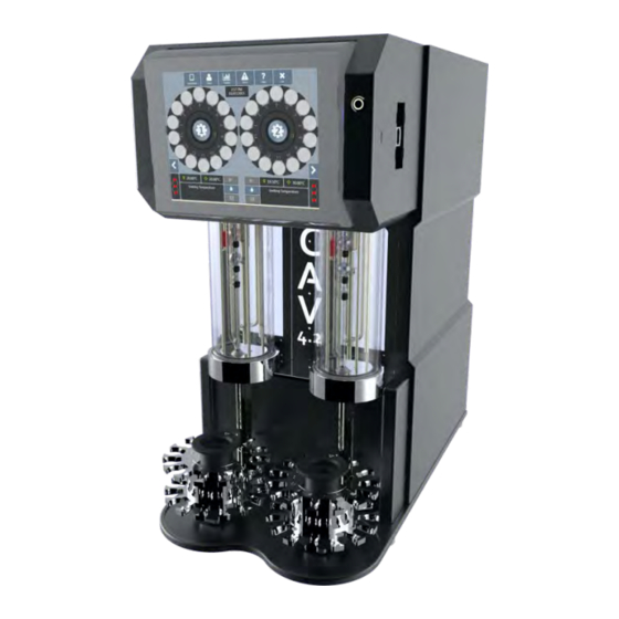
Setup the CAV 4.2 Initial setup of the CAV 4.2 involves connecting the hoses and cables and filling the baths with silicone bath fluid. See Figure 1 and Table 8. Figure 1 — Complete CAV 4.2 System Table 8 — Tools and Materials Required for Setup... -
Page 14: Connect Hoses
Waste outlets Figure 2 — Tubing Connections 1. Place the CAV 4.2 on a solid, level workbench. The workbench must be located near a MAINS AC power connection capable of providing sufficient current (10 A at 115 V ) to the CAV 4.2. -
Page 15: Figure 3 - Solvent Inlets
Screw the bottle cap onto the solvent bottle. 7. Repeat steps 4 through 6 for each piece of solvent tubing. Note: Each piece of tubing must run from the middle of the CAV 4.2 into the waste receiver. ⁄... - Page 16 Caution: Do not overtighten the waste outlet compression nut. 9. For each bath, connect the waste tubing to the CAV 4.2: a. Unscrew the brass compression nut from the waste outlet fitting. b. Thread the tubing through the compression nut.
-
Page 17: Fill Baths
20 cSt Plumbing lid Display hood Left bath Right bath Figure 4 — Temperature Baths Warning: Follow all lab policies regarding the safe handling and disposal of all hazardous materials. 1. Open the plumbing lid. CANNON Instrument Company® | Getting Started... -
Page 18: Figure 5 - Temperature Bath Details
Figure 5 — Temperature Bath Details 4. Insert the funnel into the thermometer hole in the top of the bath to be filled. See Figure 6. Fill hole Figure 6 — Bath Top (Fill Hole) | CAV 4.2 Operation Manual... -
Page 19: Connect Cables
2. Plug the power cord into the MAINS AC outlet at the work station. 3. (optional) Connect the CAV 4.2 to the network switch with one CAT cable. 4. (optional) Connect the network switch to the PC with a CAT cable and USB adapter. -
Page 20: Calibrate Temperature (Cav 4.2 Gui)
The instrument is calibrated by inserting a thermometer through an access hole in the display hood, measuring the actual temperature of the bath fluid, and entering that temperature into the CAV 4.2 software. See Table 10 for tools and materials required. -
Page 21: Figure 9 - Thermometer Access Holes
7. Click Calibrate, wait for the system to save the adjustment, and then click to return to the Back main screen. 8. Remove and clean the thermometer. 9. Repeat steps 2 through 8 for the second bath. CANNON Instrument Company® | Getting Started... -
Page 22: Set Vacuum And Pressure (Cav 4.2 Gui)
Set Vacuum and Pressure (CAV 4.2 GUI) Set the vacuum and pressure of the CAV 4.2 before running the instrument. Table 11 for tools and materials required. Table 11 — Tools and Materials Required to Set Vacuum and Pressure Description Assembled CAV 4.2... -
Page 23: Adjust The Default Wash Settings (Cav 4.2 Gui)
Run a Wash (CAV 4.2 GUI) Wash solvent through the CAV 4.2 prior to training sensors or running a test. See Table 12 for tools and materials needed. Table 12 — Tools and Materials Required to Run a Wash Description Assembled CAV 4.2... -
Page 24: Train Sensors (Cav 4.2 Gui)
Train the sensors whenever a CAV 4.2 bath is to operate at a new temperature. Once trained, the calibration values for a particular temperature are saved and will be recalled if the CAV 4.2 is set to run at that temperature again. Retraining for a particular temperature is only necessary when the viscometer tube is changed or if sensor performance changes over time. -
Page 25: Figure 15 - Train Screen
See Figure 15. Figure 15 — Train Screen Note: Do not check the boxes. Prewash Trip Points Only 4. Click Start Training. 5. When training is complete, repeat steps 1 through 4 for the second bath. CANNON Instrument Company® | Getting Started... -
Page 26: Run A Sample Test (Cav 4.2 Gui)
GUI) This test verifies system calibration and provides a technician with basic training in operating the CANNON CAV 4.2. See Table 14 for tools and materials required. Table 14 — Tools and Materials Required to Run a Sample Test Description Description Assembled CAV 4.2... -
Page 27: Review And Export Data (Cav 4.2 Gui)
A field entry screen opens. Export 4. Enter the sample filename, then click the green checkmark to submit it. A window opens. Save As 5. Select the location to which to save the data file, then click Save CANNON Instrument Company® | Getting Started... -
Page 28: Connecting With Viscpro Ii
CAV® 4.2 Operation Manual Connecting with VISCPRO II The CAV 4.2 ships from CANNON ready for deployment on a dedicated, closed network. Figure 18 displays the default settings for the closed network. Figure 18 — Closed Network Settings For other network configurations, please contact the CANNON service department. -
Page 29: Connect Equipment
If necessary, a copy of the driver is provided on the USB flash drive. 3. Connect a CAT cable from the Ethernet adapter to the network switch. 4. Connect CAT cables from each CAV 4.2 to the network switch. CANNON Instrument Company® | Connecting with VISCPRO II... -
Page 30: Install Viscpro Ii
MaxPollResponseWaitTime 2000 Maximum time in milliseconds that (2 seconds) VISCPRO waits for an instrument response when polling. MaxResponseWaitTime 20000 Maximum time in milliseconds that (20 seconds) VISCPRO waits for an instrument response. | CAV 4.2 Operation Manual... -
Page 31: Set Up Network Adapter
Allow the computer to turn off this device to save power. Click OK. 6. Right-click the connection and select Properties. The window opens. Connection Properties 7. Uncheck Internet Protocol Version 6 (TCP/IPv6). CANNON Instrument Company® | Connecting with VISCPRO II... -
Page 32: Figure 21 - Tcp/Ip Properties
11. In the top menu bar, click Settings. See Figure 22. Network Connections Advanced > Advanced Figure 22 — Advanced settings 12. Move the USB to Ethernet Connection to the last connection position. Click OK. | CAV 4.2 Operation Manual... -
Page 33: Configure Firewall Rules
In the upper right corner, under Actions, click • Rule. Select Custom. Click Next. • • Select and click Next. All programs • Change to ICMPv4. Protocol Type • Click Customize. • Select Specific ICMP types. CANNON Instrument Company® | Connecting with VISCPRO II... -
Page 34: Configure Usb Power Settings
USB settings > USB selective suspend • Under controllers, double-click on the appropriate USB Device Manager > Universal Serial Bus hub, select the tab, and uncheck Power Management Allow the computer to turn off this device to save power. | CAV 4.2 Operation Manual... -
Page 35: Cav Registry Settings
CAV Registry Settings The registry keys in Table 17 are set up at CANNON prior to shipping and should not need to be adjusted for the initial installation. However, when reconfiguring a network or adding an additional CAV 4.2 to... -
Page 36: Operation
Common instrument settings, method templates, and equipment status are shared between the programs. The operating status of the CAV 4.2 is shown on the left-most button of the main screen menu of the CAV 4.2 GUI. This button toggles between Mode. -
Page 37: Table 18 - Gui Screen Details
Click to set target temperature. Activity message Displays current activity. Preheater temperature Displays current preheater temperature. Run/Stop Click to start or stop a run. Actions Wash Click to run a wash. Pause Click to pause a run or wash. CANNON Instrument Company® | Operation... -
Page 38: Figure 24 - Main Screen
Main screen menu Carousel Carousel Slider Slider Status Status Bath 2 Bath 1 Figure 24 — Main Screen Bath screen menu Carousel Slider Figure 25 — Bath Screen | CAV 4.2 Operation Manual... -
Page 39: Viscpro® Ii Software Interface
Figure 26 shows a typical VISCPRO II interface with an open instrument window, analysis log, application specific status window, and general information status windows. Table 19 provides description for window details. Figure 26 — VISCPRO Interface Window CANNON Instrument Company® | Operation... -
Page 40: Table 19 - Viscpro Window Details
Displays a specific analysis report. Click to open the general information General status window. Click to open the VI Matching information Information Status Bar VI Matching status window. Click to open a status window for a <instrument> particular instrument. | CAV 4.2 Operation Manual... -
Page 41: Manage User Accounts (Viscpro Ii/Cav 4.2 Gui)
Manage User Accounts (VISCPRO II/CAV 4.2 GUI) VISCPRO II and CAV 4.2 GUI user accounts are independent of each another. The VISCPRO II accounts are associated with the entire software installation and are not instrument specific. Both VISCPRO II and the CAV 4.2 GUI start with three default accounts. See Table 20. -
Page 42: Setup And Edit User Accounts
Users > Logout. Connect VISCPRO II to the CAV 4.2 VISCPRO II and the CAV 4.2 must be set up and communicating prior to attempting to establish a connection. Refer to Connecting with VISCPRO II for instructions. 1. Start VISCPRO II on the PC. -
Page 43: Set Bath Temperature (Viscpro Ii)
GUI. Refer to Getting Started for more information. Calibrate Temperature (VISCPRO II) Calibrate the temperature of the CAV 4.2 whenever the instrument is moved, a new bath temperature is to be used, or the bath fluid is refilled. The instrument is calibrated by inserting a thermometer through an access hole in the display hood, measuring the actual temperature of the bath fluid, and entering that temperature into the CAV 4.2 software. -
Page 44: Train Sensors (Viscpro Ii)
Train the sensors whenever the CAV 4.2 bath is to operate at a new temperature. Once trained, the calibration values for a particular temperature are saved and will be recalled if the CAV 4.2 is set to run at that temperature again. Retraining for a particular temperature is only necessary when the viscometer tube is changed or if sensor performance changes over time. - Page 45 On the CAV 4.2 GUI, touch the Local Mode/Remote Mode button to toggle the instrument state. The icon will turn green to indicate that the CAV 4.2 has found VISCPRO VISCPRO II Menu, click Main > Poll for Instruments. If an instrument is located, an c.
- Page 46 Select Trays 7. Select the trays to run. Click The CAV 4.2 begins running the selected trays. Additional samples may be added to the trays until the run completes. • Pause—opens a selection window. Pausing a tray "Now" immediately halts all actions for that tray.
-
Page 47: View Test Results (Viscpro Ii)
The heater temperature is determined by the Preheat Temperature setting of the sample that is in the preheat position, even if that sample is set to No preheat. Set the temperature to 0 (zero) to turn off the heater. CANNON Instrument Company® | Operation... -
Page 48: Control Sample Cup Heaters
Close. Heater Duty Cycle, Parameter Value Save 3. For CAV 4.2 GUI: navigate to the appropriate Bath Screen, click Settings > Tube. 4. Enter the appropriate number of duty cycle into the field. See Sample Cup Heater Duty Cycle Table 22 for starting reference but note actual number may vary between instruments. -
Page 49: Advanced Setup
Viscometer tube calibration values are associated with specific temperatures, so calibration must be performed when operating a CAV 4.2 bath at a new temperature. Once a tube is calibrated at a particular temperature, the C and E constants are saved by the instrument and will be recalled if that tube is set to run at that temperature again. -
Page 50: Method/Test Settings
Method/Test Settings Method templates are stored in the registry of the CAV 4.2. When an instance of VISCPRO II connects with a CAV 4.2, those method templates are pushed to VISCPRO II. Any changes made to the method templates in VISCPRO II are synchronized with the CAV 4.2. No method templates are permanently stored with VISCPRO II. -
Page 51: Table 23 - Method Settings: Test
The heater temperature is determined by the Preheat Temperature setting of the sample that is in the preheat position, even if that sample is set to No preheat. Set the temperature to 0 (zero) to turn off the heater. CANNON Instrument Company® | Advanced Setup... -
Page 52: Table 24 - Method Settings: Wash
Number of solvent A washes for B-Pipe B-Pipe Solvent B Washes Number of solvent B washes for B-Pipe B-Pipe Solvent C Washes Number of solvent C washes for B-Pipe B-Pipe Dry Time Time(sec) to force air dry B-Pipe | CAV 4.2 Operation Manual... -
Page 53: Table 25 - Method Settings: Advanced
Bulb 3 Vent Drain Time Time (sec) for a bulb 2 sample between when the tube vent is opened to atmosphere and the sample efflux starts CANNON Instrument Company® | Advanced Setup... -
Page 54: Table 26 - Method Settings: Drop Criteria
If 'Use Percent Difference' and 'Use Efflux Difference' are both set, then, if true, a match between two determinations is made if either criteria is met; else if false, both criteria must be met to produce a matched set. | CAV 4.2 Operation Manual... -
Page 55: Adjust Default Wash Settings
Configure > [instrument group] > [instrument] > Tray Settings: Default Wash. The Tray Settings: Default Wash window opens. • Select the tube to edit. For CAV 4.2 GUI: navigate to the appropriate Bath Screen, click • Settings > Default Wash. Create a Standard CAV Data Table Analysis An analysis is used to view detailed data stored in the VISCPRO II database. -
Page 56: Table 27 - Cav Data Table Fields
Viscosity Data Display KV Check Data Check to display sample run with Verify Known KV method Max KV % Difference When the % Diff KV exceeds this value, an "X" is displayed in the TOL column | CAV 4.2 Operation Manual... -
Page 57: Maintenance And Service
• UI updater: this software is actually the complete UI updater program (UpdateUI.exe) that runs on the CAV 4.2. It is used to install the UI software and firmware updates. It is updated by copying it over the existing UpdateUI.exe. -
Page 58: Update The Ui Software
5. Click OK. The baths are placed into Bootloader mode (orange lights), and the Windows logon screen displays. 6. Click Updates. The update shell opens. 7. Plug the prepared USB flash drive into the USB connection 8. Click Update Firmware. 9. Select the type of controller to update. Windows Explorer opens. | CAV 4.2 Operation Manual... -
Page 59: Update The Viscpro Ii Software
Do not drain the silicone bath fluid until it has cooled off to a safe temperature. 1. Turn off the CAV 4.2 and allow the bath to cool down. 2. Drain the silicone bath fluid into a clean container and save for refilling the unit. -
Page 60: Replace Power Supply
19. Calibrate the new viscometer tube. Replace Power Supply The CAV 4.2 power supply is a switching regulated power supply designed to handle 90 – 240 V . To accommodate different locales, only the MAINS AC power cable needs to be changed. -
Page 61: Adjust Solvent Dosing Chamber Sensors
Adjust Solvent Dosing Chamber Sensors Each CAV 4.2 bath has its own solvent dosing chamber, mounted on the side panel. Optical sensors on the inlet and the outlet of the dosing chasing must be adjusted to "see" the solvents that are drawn past them. -
Page 62: Warranty
Company to conform to the weight, specifications and standards stated on the package. Returning a Product to CANNON Before returning a CANNON product for repair or service, make every attempt to identify the problem. If, after careful checking, the problem remains unidentified or unsolved, telephone CANNON Instrument Company (or the local service agent) to consult with a product specialist. -
Page 63: Required Information
Please contact CANNON before returning a product that could possibly contain hazardous material. Shipping Notification Products returned without CANNON’s prior authorization will not be accepted. The customer may be billed a testing fee if a product is returned to CANNON and found to be working properly. CANNON Instrument Company® | Warranty... - Page 64 CANNON INSTRUMENT COMPANY® 2139 High Tech Road | State College, PA 16803 | USA 800-676-6232 | 814-343-8000 | Fax: 814-353-8007 sales@cannoninstrument.com | www.cannoninstrument.com...
Need help?
Do you have a question about the CAV 4.2 and is the answer not in the manual?
Questions and answers