Table of Contents
Advertisement
Quick Links
Advertisement
Table of Contents

Subscribe to Our Youtube Channel
Related Manuals for Cannon UltraVIS 192


Summary of Contents for Cannon UltraVIS 192
- Page 2 Copyright Copyright © 2021 CANNON Instrument Company®. All rights reserved. Trademarks CANNON® and the CANNON logo are registered trademarks of CANNON Instrument Company. Contact Address: CANNON Instrument Company 2139 High Tech Road State College PA 16803, USA Phone: 1-814-353-8000; 1-800-676-6232...
-
Page 3: Table Of Contents
Proper Shutdown ......................33 Warranty ........................34 Products Limited Warranty ......................34 Reagent and Chemical Warranty ....................34 Returning a Product to CANNON ....................34 Required Information ......................35 Hazardous Materials ....................... 35 Shipping Notification ......................35 CANNON Instrument Company® | Contents... -
Page 4: List Of Figures
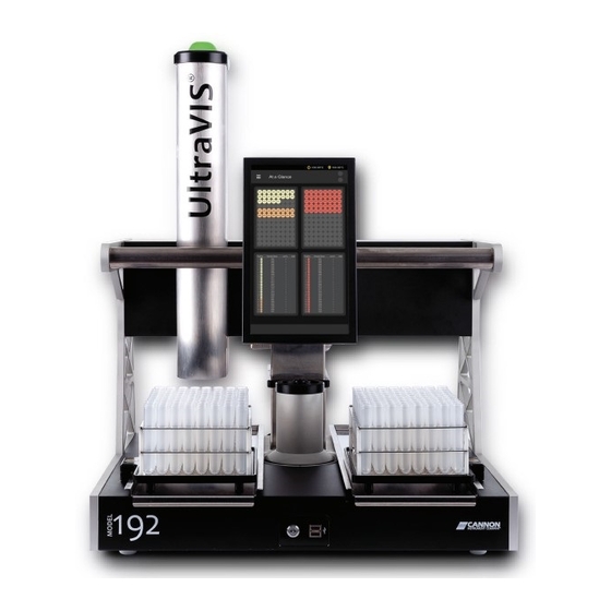
List of Figures Figure 1 — UltraVIS 192 High Speed, Solvent-Free Kinematic Viscometer ........1 Figure 2 — UltraVIS Components ...................... 6 Figure 3 — Rear Connections with MAINS Power ................7 Figure 4 — Vacuum Pump Connections..................... 7 Figure 5 — Vacuum Control Pump..................... 8 Figure 6 —... - Page 5 Table 3 — Packing List (Installation) ....................5 Table 4 — Packing List (Spares) ......................5 Table 5 — Beacon Light Descriptions ....................9 Table 6 — Temperature Calibration Tools and Materials ..............9 CANNON Instrument Company® | List of Tables...
-
Page 7: Overview
UltraVIS Operation Manual Overview The CANNON UltraVIS® 192 (referred to as “UltraVIS”) is a fully automated, high speed, solvent-free viscometer for rapid kinematic viscosity measurement of transparent and opaque liquids with ASTM D445 precision capability. A 192-position sample handler (comprised of two 96-position trays) allows unattended processing of up to 30 samples per hour. -
Page 8: Specifications / Compliances
Specifications / Compliances Table 1 — Specifications and Compliances Specifications Details Model UltraVIS High Speed, Solvent-Free Kinematic Viscometer Methodology Correlates with ASTM D445/D446, ISO 3104/3105, IP 71 Applications In-service oil viscosity, used oil analysis, fleet maintenance, condition monitoring Dimensions (W × D × H) Unit: 60.9 cm ×... -
Page 9: Notes / Cautions / Warnings
Make sure that you read and understand all operating instructions and safety precautions listed in • this manual before installing or operating your unit. Direct questions regarding instrument operation or documentation to CANNON Instrument Company. Do not deviate from the installation, operation, or maintenance procedures described in this •... -
Page 10: Getting Started
USB for future retrieval and reporting. Unpack and Inspect Unpack and inspect the complete CANNON UltraVIS and all accessories as soon as they are received. Caution: Many components are fragile. Use caution when moving and handling the UltraVIS and accessories. -
Page 11: Table 3 - Packing List (Installation)
83.0018 Fuse, 2A 30.0040 Fuse, 4A 74.4025 Pad, Tray Carrier 83.0192 83.0371 UltraVIS Transporter to Cell Alignment UltraVIS Transporter to Sample Rack Alignment 83.0372 Viscometer Cell Nut 83.0402 83.0019 Wiper Seal, Transporter Syringe Tube CANNON Instrument Company® | Getting Started... -
Page 12: Figure 2 - Ultravis Components
Beacon Light Touchscreen Gantry Backpack Viscometer Cell Sample Trays Assembly Power Button USB Ports Figure 2 — UltraVIS Components | ULTRAVIS Operation Manual... -
Page 13: Setup The Ultravis
2. Plug the power cord into the MAINS AC outlet at the work station, ensuring power requirements comply with instrument needs. Next, connect the Vacuum Pump and Vacuum Control Pump. Connect Vacuum Pump Connect tubes and power cable to Vacuum Pump. See Figure 4. Figure 4 — Vacuum Pump Connections CANNON Instrument Company® | Getting Started... -
Page 14: Connect Vacuum Control Pump
Connect Vacuum Control Pump 1. Connect tubing to Vacuum Control Pump. See Figure 5. Figure 5 — Vacuum Control Pump 2. Next, route waste to Waste Receiver. Route Waste to Waste Receiver 1. Place the waste receiver beneath the UltraVIS. In order to promote proper gravity drainage, the top of the waste receiver must be lower than the waste outlets on the back of the instrument. -
Page 15: Beacon Lights
Refer to Table 6 for necessary tools and materials. Table 6 — Temperature Calibration Tools and Materials Description Part Number Assembled UltraVIS 9729-A00, -A05, -A10 UltraVIS Calibration Kit (Digital Thermometer, Probe, Adaptor, 83.0420 Cradle, Probe, and 10 Syringes) CANNON Instrument Company® | Getting Started... -
Page 16: Figure 8 - At A Glance Screen
1. First, you will need to move the position of the gantry in order to have access to the Viscometer Cell Assembly. From the main screen, Glance, use a single touch to select the “hamburger” or At a three-line button in top left corner next to the title Glance, to view the Main Menu Screen. -
Page 17: Figure 10 - Gantry Control Screen
Figure 10 — Gantry Control Screen 4. Return to the main menu by using the back arrow key in the upper left hand corner. Then, navigate to the temperature calibration screen. See Figure 11. Figure 11 — Calibrate Temperature CANNON Instrument Company® | Getting Started... -
Page 18: Figure 12 - Adaptor Placement
5. Next, place the adaptor on top of the Viscometer Cell Assembly, as shown in Figure 12. Then, place the cradle over the adaptor, as shown in Figure 13, making sure the access hole lines up with the access hole on the adaptor. Adaptor Cradle Figure 13 —... -
Page 19: Figure 15 - Inject Viscosity Standard N100
Checkmark. See Figure 16 and Figure 17. Green Figure 17 — Enter Thermometer Temperature Figure 16 — Edit Temperature Button Reading 9. The temperature of your UltraVIS is now calibrated. Remove and clean thermometer, then store safely. CANNON Instrument Company® | Getting Started... -
Page 20: Setting Standards
Setting Standards Setting standards is necessary in order to run standards and calibrate the UltraVIS. 1. From the main screen, Glance, use a single touch to select the “hamburger” or three-line At a button in top left corner next to the title Glance, to view the Screen. -
Page 21: Figure 19 - Ultravis Menu/Settings
Screen, use a single touch on the three dots, on the upper right hand side of Standards screen, to access the Menu. See Figure 20. Standards Figure 20 — UltraVIS Menu/Settings/Standards 5. From the Menu, select New. See Figure 21. Standards CANNON Instrument Company® | Getting Started... -
Page 22: Figure 21 - Ultravis Add New Standard
Figure 21 — UltraVIS Add New Standard 6. From the screen, use a single touch to select the arrow next to Item. See Figure 22. Add New Figure 22 —Name New Standard 7. Use the touchscreen keyboard to enter the name of your Standard. Once finished, use a single touch to select the Green Checkmark. -
Page 23: Figure 23 - Naming Standards Screen
Once finished, use a single touch to select the and return Back Arrow to the screen. See Figure 24. At a Glance Select to return to Main Menu. Figure 24 — Standard Added CANNON Instrument Company® | Getting Started... -
Page 24: Calibrate Viscometer
Calibrate Viscometer The UltraVIS comes pre-calibrated from CANNON. However, if you choose to recalibrate the viscometer, follow the procedure outlined in this section. You must choose at least three known standards for Setting Standards recalibration. If you have not yet set standards on your instrument, refer to the section of this manual. -
Page 25: Figure 26 - Select Calibrate Viscometer
Viscometer Setting Standards have not yet set standards on your instrument, refer to the section of this manual before proceeding. Note the C and E constants change based upon your selection. See Figure 28. CANNON Instrument Company® | Getting Started... -
Page 26: Figure 28 - Select At Least Three Known Standards
Choose at least three different standards. C and E constants change based upon the selection. Figure 28 — Select at Least Three Known Standards 5. Once you have made the selection of at least three known standards, select the green Commit button. -
Page 27: Run A Sample
Target Temperature Actual Temperature Connected Back to Home Switch between tray 1 and tray 2 Backpack Sample cells selected for testing Test Status Abort Test Pause Testing Figure 30 — Touchscreen Tray 1 Overview CANNON Instrument Company® | Run a Sample... -
Page 28: Procedure
Procedure 1. Fill sample vial to above the tray line (where the top of the tray meets the vial) but below the top of the vial, see Figure 31. Then place tray on instrument for testing. Note: When a sample is drawn from the vial, the liquid will be displaced. DO NOT fill sample to the top of the vial because it will cause spillage when the sample is drawn. -
Page 29: Figure 32 - Choose Tray
Touch again to deselect. Once all samples for one group are highlighted, select Add. See Figure 33. Note: If you highlighted the incorrect circles, press to deselect Cancel everything that is highlighted. Or, to remove individual highlights, touch the individual circle. CANNON Instrument Company® | Run a Sample... -
Page 30: Figure 33 - Add Sample Group
Samples Selected Figure 33 — Add Sample Group 4. Once the Sample Group has been added, enter the Name. When finished, move to the Sample next screen by selecting the Checkmark. See Figure Green Enter Sample Name Select Figure 34 — Sample Name 5. -
Page 31: Figure 35 - Starting Index
6. To add a Standard, select the button for each highlighted sample group and then choose Standard the appropriate standard. See Figure 36 and Figure 36 Select Sample Group Standard Figure 36 — Set Standard for Sample Group CANNON Instrument Company® | Run a Sample... -
Page 32: Figure 37 - Select Standard For Sample Group
Choose Standard Figure 37 — Select Standard for Sample Group 7. Repeat steps three through five for all sample groups (and step six for standards). The software will display each sample group in a different color for easy identification of groups. See Figure 38. Figure 38 —... -
Page 33: Figure 39 - Remove Samples
See Figure 39. Select Sample Remove Figure 39 — Remove Samples 9. Once all the samples to be tested have been entered, press Start. See Figure 40. Start Figure 40 — Start Sample Testing CANNON Instrument Company® | Run a Sample... -
Page 34: Figure 41 - Load For Tray 2
10. Once is pressed, the tray slides back into place, the Gantry moves to the selected vial in the Start sample tray and injects the sample into the viscometer cell twice; the first sample drop cleans the cell, the second drop is measured. 11. -
Page 35: Figure 42 - Sample And Test Status
(the home screen) provides information for sample testing for both trays as At a Glance well as results. See Figure 43. Tray 1 Tray 2 Tray 1 Results Tray 2 Results Figure 43 — GUI “At a Glance” CANNON Instrument Company® | Run a Sample... -
Page 36: Review And Export Data
Review and Export Data 1. To review individual detailed information, press and hold down on a sample in the screen, as Tray shown in Figure 44. Press and hold for detailed sample information. Figure 44 — Single Sample Results 2. All samples results from a particular tray may be viewed from the screen. -
Page 37: Figure 46 - Return To Main Menu
Screen. See Figure At a Figure 46 — Return to Main Menu b. From the Main Menu, choose Export. The menu will expand, choose Data. See Figure 47. Export Figure 47 — Export Data Menu CANNON Instrument Company® | Run a Sample... -
Page 38: Figure 48 - Export To Usb Drive
c. The UltraVIS will prompt you to insert a USB drive. Insert your USB drive into the port on the front of the instrument. See Figure 2. d. Once you have inserted your drive, select and your data will be transferred from the Export instrument to your USB drive in CSV format. -
Page 39: Proper Shutdown
UltraVIS Operation Manual Proper Shutdown Press the OFF power button on the front of unit. Figure 49 — Power Off Instrument CANNON Instrument Company® | Proper Shutdown... -
Page 40: Warranty
Company to conform to the weight, specifications and standards stated on the package. Returning a Product to CANNON Before returning a CANNON product for repair or service, make every attempt to identify the problem. If, after careful checking, the problem remains unidentified or unsolved, telephone CANNON Instrument Company (or the local service agent) to consult with a product specialist. -
Page 41: Required Information
Please contact CANNON before returning a product that could possibly contain hazardous material. Shipping Notification Products returned without CANNON’s prior authorization will not be accepted. The customer may be billed a testing fee if a product is returned to CANNON and found to be working properly. CANNON Instrument Company® | Warranty... - Page 42 CANNON INSTRUMENT COMPANY® 2139 High Tech Road | State College, PA 16803 | USA 800-676-6232 | 814-343-8000 | Fax: 814-353-8007 sales@cannoninstrument.com | www.cannoninstrument.com...
Need help?
Do you have a question about the UltraVIS 192 and is the answer not in the manual?
Questions and answers