Table of Contents
Advertisement
Advertisement
Table of Contents

Related Manuals for Cannon CAV-2100


Summary of Contents for Cannon CAV-2100
- Page 1 CAV®-2100/2200 Automatic Viscometer Installation Guide...
-
Page 3: Table Of Contents
Coolant connections ..................... 12 Sample trays/drains ....................13 Splash guards ......................14 Ventilation exhaust shroud ................... 14 ® Automatic Viscometer Models CAV-2100 and CAV-2200 Installation & Setup Guide CANNON Version 1.3g— August, 2011; CANNON ® Instrument Company 2139 High Tech Road • State College, PA 16803 • USA... - Page 4 Procedure .......................... 29 Connecting components ..................29 Completing RS-485 connections ................29 APPENDIX B—Tubing connections/photography ® Automatic Viscometer Models CAV-2100 and CAV-2200 Installation & Setup Guide CANNON Version 1.3g— August, 2011; CANNON ® Instrument Company 2139 High Tech Road • State College, PA 16803 • USA...
-
Page 5: Customer Pre-Installation Checklist For The Cannon Automatic Viscometer
This chapter uses a checklist format to detail the required utilities, accessories, clearances, personnel and training issues to be considered prior to, and during installation of the CAV-2100 instrument(s) in your facility. Please review the checklist carefully and address any outstanding issues to facilitate a successful installation. - Page 6 The laboratory must be equipped with all of the standard safety features normally associated with use of solvents, corrosives, etc. ® Automatic Viscometer Models CAV-2100 and CAV-2200 Installation & Setup Guide CANNON Version 1.3g— August, 2011; CANNON ®...
-
Page 7: Additional Installation Requirements
Training and calibration will require 2-3 days. The customer should be prepared to supply typical samples for running tests during the training process. ® Automatic Viscometer Models CAV-2100 and CAV-2200 Installation & Setup Guide CANNON Version 1.3g— August, 2011; CANNON ®... - Page 8 FEP. All samples/solvents used with the CAV must be compatible with these materials. 6.___Computer In the event that the controlling computer is not supplied by CANNON ® refer to the computer specification sheet or contact CANNON ®...
-
Page 9: Cav Installation
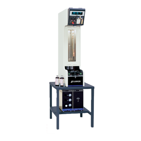
For information on multiple-unit installations, consult APPENDIX A and the enclosed diagram(s). The Bath Unit for the CAV-2100 or the CAV-2200 may be placed on the benchtop or a ® specially-designed pedestal base, available from CANNON CAV-2000 single and dual-bath installation on pedestal base ®... -
Page 10: Cav Components
The CAV-2100 contains two viscometers within a single bath. The CAV-2200 contains twin baths, each with one viscometer tube. -
Page 11: Unpacking Components
D Crate with Bath Unit removed (Relocate Bath Unit to pedestal or benchtop) E Bath Unit in upright (installed) position (See notes following) ® Automatic Viscometer Models CAV-2100 and CAV-2200 Installation & Setup Guide CANNON Version 1.3g— August, 2011; CANNON ® Instrument Company... -
Page 12: Arranging Components
CAV components will be necessary during setup. If you are completing a multiple unit configuration, refer to the Appendix of this Guide for further information on setup options. ® Automatic Viscometer Models CAV-2100 and CAV-2200 Installation & Setup Guide CANNON Version 1.3g— August, 2011; CANNON ®... -
Page 13: Bath Unit Connections
Multiple CAV instruments may be networked to a single computer via RS-485 cable connections available with the Multi-Unit Interface Kit. See APPENDIX A for more information. ® Automatic Viscometer Models CAV-2100 and CAV-2200 Installation & Setup Guide CANNON Version 1.3g— August, 2011; CANNON ®... -
Page 14: Power Connection
Instrument Company. The viscosity of the fluid depends upon the temperature of the bath during most operations: C ° C ° ® Automatic Viscometer Models CAV-2100 and CAV-2200 Installation & Setup Guide CANNON Version 1.3g— August, 2011; CANNON ® Instrument Company... - Page 15 Loosen and remove the screws securing the top rear cover to the CAV Bath Unit. Then remove the cover. 2. (CAV-2100 instrument only) If the bath is empty, remove the plug/ ® cap from the Swagelok fitting at the front of the top bath flange.
-
Page 16: Coolant Connections
When cooling devices are in use, the fitting secures a convenient fill tube for bath fluid. Remove the fill tube before installing your cooling device! ® Automatic Viscometer Models CAV-2100 and CAV-2200 Installation & Setup Guide CANNON Version 1.3g— August, 2011; CANNON ®... -
Page 17: Sample Trays/Drains
2 centimeters (3/4”) over the edge of the sample table. The forward edge of an unheated tray will be indented approximately 2.2 centimeters (7/8”). ® Automatic Viscometer Models CAV-2100 and CAV-2200 Installation & Setup Guide CANNON Version 1.3g— August, 2011; CANNON ®... -
Page 18: Splash Guards
Bath Unit frame in front of the viscometer tube tip. The felt pad should face the tube tip (see photo, previous page). ® Automatic Viscometer Models CAV-2100 and CAV-2200 Installation & Setup Guide CANNON Version 1.3g— August, 2011; CANNON ®... -
Page 19: Ventilation Exhaust Shroud
Service Unit. The compressor must be capable of producing a constant flow of 3 cfm (5 m /hr) at 40 psi (275 kPa). A water trap and air filter ® Automatic Viscometer Models CAV-2100 and CAV-2200 Installation & Setup Guide CANNON Version 1.3g— August, 2011; CANNON ®... -
Page 20: Optional Nitrogen Connection
Do not turn on the Service Unit power switch until all connections have been completed correctly and the SDU has been properly grounded. ® Automatic Viscometer Models CAV-2100 and CAV-2200 Installation & Setup Guide CANNON Version 1.3g— August, 2011; CANNON ®... -
Page 21: Other Options For House Air/Nitrogen/Vacuum
Bath Unit using the existing screws. CAUTION Do not operate this unit before verifying correct installation of the ground strap. ® Automatic Viscometer Models CAV-2100 and CAV-2200 Installation & Setup Guide CANNON Version 1.3g— August, 2011; CANNON ® Instrument Company... -
Page 22: Solvent Connections (Single And Dual Solvent Systems)
Solvent Dispensing Unit. Insert ® one end of the 1/4”-OD Poly-Flo solvent tube into the user’s washing ® Automatic Viscometer Models CAV-2100 and CAV-2200 Installation & Setup Guide CANNON Version 1.3g— August, 2011; CANNON ® Instrument Company... -
Page 23: Waste Can Connections
(con- forming to local safety regulations), making certain that gravity flow is unimpeded (no loops or knots). ® Automatic Viscometer Models CAV-2100 and CAV-2200 Installation & Setup Guide CANNON Version 1.3g— August, 2011; CANNON ®... -
Page 24: Adjusting Pneumatic Controls
CAV. These controls adjust the air pres- sure used to regulate the speed at which respective mechanisms move. ® Automatic Viscometer Models CAV-2100 and CAV-2200 Installation & Setup Guide CANNON Version 1.3g— August, 2011; CANNON ®... - Page 25 RETURN regulators to ensure that the cylinders can extend fully. After adjustments are complete, close the hinged access panel. NOTE Closing the access panel will also lock it. ® Automatic Viscometer Models CAV-2100 and CAV-2200 Installation & Setup Guide CANNON Version 1.3g— August, 2011; CANNON ® Instrument Company...
-
Page 26: Installing Viscpro ® Software
VISCPRO executable file on your ® Windows desktop. ® Automatic Viscometer Models CAV-2100 and CAV-2200 Installation & Setup Guide CANNON Version 1.3g— August, 2011; CANNON ® Instrument Company 2139 High Tech Road • State College, PA 16803 • USA... -
Page 27: Software Configuration
3. Click on the (arrow) on the right side of the User Name: list box to display the list of registered users. ® Automatic Viscometer Models CAV-2100 and CAV-2200 Installation & Setup Guide CANNON Version 1.3g— August, 2011; CANNON ®... -
Page 28: Checking Instrument Settings
CAV trays and tests. Use the ID field to input instrument identification information using up to 30 alphanumeric characters. ® Automatic Viscometer Models CAV-2100 and CAV-2200 Installation & Setup Guide CANNON Version 1.3g— August, 2011; CANNON ® Instrument Company... -
Page 29: Tray Settings: Tube And Bath
Click on the Fast Run Tube check box if the viscometer tube is the fast run (dual bulb) type. ® Automatic Viscometer Models CAV-2100 and CAV-2200 Installation & Setup Guide CANNON Version 1.3g— August, 2011; CANNON ® Instrument Company... - Page 30 If the Always perform maximum determinations radio button is selected, the last two flow times will be used for the viscosity determination. ® Automatic Viscometer Models CAV-2100 and CAV-2200 Installation & Setup Guide CANNON Version 1.3g— August, 2011; CANNON ®...
-
Page 31: Tray Settings: Wash
The Solvent fill time(s) setting determines the amount of time that solvent will be introduced into the viscometer tube during each rinse cycle. Acceptable values are 1 to 30 seconds. ® Automatic Viscometer Models CAV-2100 and CAV-2200 Installation & Setup Guide CANNON Version 1.3g— August, 2011; CANNON ®... -
Page 32: Testing The Configuration
When all CAV units have been configured, verify a successful configura- tion by running a sample in Remote mode for each instrument per manual instructions. ® Automatic Viscometer Models CAV-2100 and CAV-2200 Installation & Setup Guide CANNON Version 1.3g— August, 2011; CANNON ®... -
Page 33: Appendix A-Multi-Unit Configuration
1. Make sure the power is removed from the computer and all instru- ments to be configured. 2. Locate the RS-485 converter and required RJ-45 connecting cable(s). ® Automatic Viscometer Models CAV-2100 and CAV-2200 Installation & Setup Guide CANNON Version 1.3g— August, 2011; CANNON ®... - Page 34 CAV instruments, make certain to enter the appropriate RS-485 address for each corresponding Bath Unit, as well as the Bath Unit serial number. ® Automatic Viscometer Models CAV-2100 and CAV-2200 Installation & Setup Guide CANNON Version 1.3g— August, 2011; CANNON ®...
-
Page 35: Appendix B-Tubing Connections/Photography
CANNON Service Unit and SDU-200 Solvent Dispensing Unit connections ® Automatic Viscometer Models CAV-2100 and CAV-2200 Installation & Setup Guide CANNON Version 1.3g— August, 2011; CANNON ® Instrument Company 2139 High Tech Road • State College, PA 16803 • USA... - Page 36 CAV-2000 upper rear panel solvent connections (RS-485 multi-bath communication cable also visible) NOTE: Copper tubing may be replaced with FEP CAV-2000 lower rear panel with exhaust manifolds and power cable in place ® Automatic Viscometer Models CAV-2100 and CAV-2200 Installation & Setup Guide CANNON Version 1.3g— August, 2011; CANNON ®...
- Page 38 CANNON INSTRUMENT COMPANY® 2139 High Tech Road | State College, PA 16803 | USA 800-676-6232 | 814-343-8000 | Fax: 814-353-8007 sales@cannoninstrument.com | www.cannoninstrument.com...
Need help?
Do you have a question about the CAV-2100 and is the answer not in the manual?
Questions and answers