Table of Contents
Advertisement
Quick Links
Advertisement
Table of Contents

Related Manuals for Cannon CAV 4.1


Summary of Contents for Cannon CAV 4.1
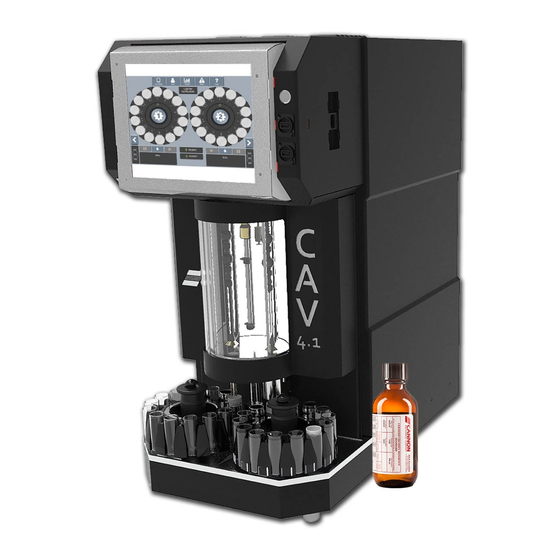
- Page 1 ® Single-Bath Automated Kinematic Viscometer Operation Manual...
- Page 2 Copyright Copyright ©2022 Cannon Instrument Company®. All rights reserved. Trademarks CANNON® and the CANNON logo, Cannon Instrument Company®, CAV®, and VISCPRO® are registered trademarks of Cannon Instrument Company. Contact Address: CANNON Instrument Company 2139 High Tech Road State College PA 16803, USA Phone: 1-814-353-8000;...
-
Page 3: Table Of Contents
Safety Precautions ........................3 Navigating the Manual ........................3 Getting Started ......................... 4 Unpack and Inspect ........................4 Setup the CAV 4.1 ......................... 6 Connect Hoses .......................... 7 Fill the Bath ..........................9 Drain the Bath ......................... 12 Connect Cables ........................15 Set Bath Temperature (Touchscreen) .................. - Page 4 VISCPRO II Software Interface ....................44 Manage User Accounts (VISCPRO II/CAV 4.1 GUI Touchscreen) ..........45 Log In ............................46 Change Password ........................46 Setup and Edit User Accounts ....................46 Logout ............................ 47 Connect VISCPRO II to the CAV 4.1 ..................... 47 Preheat Option ...........................
- Page 5 List of Figures Figure 1 — Complete CAV 4.1 System Setup ..................6 Figure 2 — Tubing Connections (Rear Close Up) ................7 Figure 3 — Back of CAV 4.1 ....................... 8 Figure 4 — Filling and Draining the Bath ................... 9 Figure 5 —...
- Page 6 Figure 51 — Connection Properties Window ................... 37 Figure 52 — TCP/IP properties Figure 53 — Advanced Settings ..........38 Figure 54 — CAV 4.1 Main Screen Menu ..................42 Figure 55 — Bath Screen ......................... 44 Figure 56 — VISCPRO Interface Window ..................44 List of Tables Table 1 —...
-
Page 7: Overview
/s (cSt) and 10,000 mm /s (cSt) from 20 °C to 150 °C (with available options.) The CAV 4.1 combines CANNON quality and reliability with a modern design and unique features to enhance lab productivity, reduce costs, and improve data quality. -
Page 8: Specifications/Compliances
Specifications/Compliances Table 1 — Specifications and Compliances Specifications Details Model CAV 4.1 Benchtop Kinematic Viscometer Methodology ASTM D445/D446, ISO 3104/3105, IP 71 Applications Formulated oil analysis, hydraulic oil analysis, additive analysis, marine fuel testing, base stock analysis, light and heavy fuel testing, waxes/paraffin, crude oil testing, glycols Dimensions (W ×... -
Page 9: Safety Precautions
• Navigating the Manual Since the CAV 4.1 uses both a touchscreen interface on the instrument and the VISCPRO II computer software application, the instructions are broken into sections for each type of controlling software. The header of each section notes so the operator knows whether CAV 4.1 GUI Touchscreen... -
Page 10: Getting Started
CAV® 4.1 Operation Manual Getting Started This chapter covers all steps necessary to set up, calibrate, and run a sample on the CAV 4.1. The procedures are intended to be performed in the order written. These are basic, simplified procedures designed to familiarize an operator with the instrument, with more detailed instructions provided in following sections. -
Page 11: Table 3 - Packing List (Installation)
Table 4 — Packing List (Tools) Description Part Number ⁄ " Allen wrench 27.1340 ⁄ " Allen wrench 68.0464 Rubber stoppers (3) 11.3115 Tubing cutter 81.1074 Yellow Tygon tubing (2 ft) 71.4.16 ⁄ " wrench ---- CANNON Instrument Company® | Getting Started... -
Page 12: Setup The Cav 4.1
Setup the CAV 4.1 Initial setup of the CAV 4.1 involves connecting the hoses and cables, and filling the bath with silicone bath fluid. See Figure 1 and Table 5. Figure 1 — Complete CAV 4.1 System Setup Table 5 — Tools and Materials Required... -
Page 13: Connect Hoses
Waste Line Figure 2 — Tubing Connections (Rear Close Up) 1. Place the CAV 4.1 on a solid, level workbench located near a MAINS AC power connection capable of providing sufficient current (10 A at 115 V ) to the CAV 4.1. Depending on the materials tested, solvent used, and laboratory regulations, the work area may also need to be equipped with a ventilation system. -
Page 14: Figure 3 - Back Of Cav 4.1
Screw the bottle cap onto the solvent bottle. 7. Repeat steps 4 through 6 for each piece of solvent tubing. Note: Each piece of tubing must run from the middle of the CAV 4.1 into the waste receiver. ⁄... -
Page 15: Fill The Bath
10 cSt 101 °C to 150 °C 20 cSt Display Hood Bath Figure 4 — Filling and Draining the Bath Warning: Follow all lab policies regarding the safe handling and disposal of all hazardous materials. CANNON Instrument Company® | Getting Started... -
Page 16: Figure 5 - Remove Float From Top Of Bath To Reveal Opening
Bath Drainage Receptacle Procedure 1. Turn off power to the CAV 4.1 instrument and let the bath cool to room temperature. 2. Lift the hood to access the top of the bath. 3. Remove the float from the top of the bath and set aside. This provides the opening to fill the bath. -
Page 17: Figure 7 - Filling Bath With 10 Cst Silicone Fluid
(135 °C and above). Refer to Figure 7 and Figure 8. Figure 7 — Filling Bath with 10 cSt Silicone Fluid Top Fill Line Bottom Fill Line (for lower temperatures) (temperatures ≥ 135 °C Figure 8 — Bath Filled to Top Fill Line CANNON Instrument Company® | Getting Started... -
Page 18: Drain The Bath
(ambient temperature) prior to working or emptying bath fluid. 2. Lift the CAV 4.1 hood to access the bath. It flips up, as shown in Figure 9. Figure 9 — Lift the CAV 4.1 Hood... -
Page 19: Figure 10 - Remove Front Panel And Set Aside
3. Remove the front panel of the CAV 4.1 by gently pulling it away from the front of the instrument, as shown in Figure 10. Set the front panel aside. Figure 10 — Remove Front Panel and Set Aside 4. Insert one end of the yellow tubing onto bath drain, leaving at least ¼" above the hose on the nozzle. -
Page 20: Figure 12 - Hose Draining Into Fluid Container
6. Use the ¼" Open End wrench to gently open the drain by turning the exposed portion counter- clockwise. ¼" Open End wrench applied to exposed drain to open Figure 13 — Open Drain with Allen Wrench and Close-Up | CAV 4.1 Operation Manual... -
Page 21: Connect Cables
2. Plug the power cord into the MAINS AC outlet at the work station. 3. (optional) Connect the CAV 4.1 to the network switch with one CAT cable. 4. (optional) Connect the network switch to the PC with a CAT cable and USB adapter. -
Page 22: Set Bath Temperature (Touchscreen)
1. From the main screen, click the target temperature button for the bath. This opens the temperature settings screen. Actual Temperature Target Temperature Figure 16 — Main CAV 4.1 Screen 2. Select button. This opens the Enter Target Temperature screen. Target Temperature Select Target Temperature Figure 17 —... -
Page 23: Calibrate Temperature (Touchscreen)
CAV 4.1 software. Refer to Table 8 for necessary tools and materials. Table 8 — Tools and Materials Required... -
Page 24: Figure 19 - Thermometer Access Hole
4. From the main screen, click the current bath temperature button for the bath. This opens screen, as shown in Figure 20. Temperature Calibration Figure 20 — Temperature Calibration Screen 5. Click the field. A field entry screen opens. Reference Temperature | CAV 4.1 Operation Manual... -
Page 25: Set Vacuum And Pressure (Components)
8. Remove and clean the thermometer, and then store safely. Set Vacuum and Pressure (Components) Set the vacuum and pressure of the CAV 4.1 before running the instrument. Use the following procedure to access the vacuum and pressure knobs within the instrument. -
Page 26: Figure 23 - Access Pin On One Side
Figure 23 — Access Pin on One Side 3. Gripping the access pins, push against the outer chassis to pull out the inner chassis. Figure 24 — Pull Out Chassis while Pulling Up Both Access Pins | CAV 4.1 Operation Manual... -
Page 27: Figure 25 - Side Of Chassis With Latch, With Close Up Of Latch
5. As the bath control wing swings out it allows access to the Vacuum and Pressure knobs. Adjust as necessary. Figure 27 shows the gauge, Figure 28 displays the knobs for adjusting vacuum and pressure. Figure 26 — Side View of Open Bath Control Wing CANNON Instrument Company® | Getting Started... -
Page 28: Figure 27 - Vacuum/Pressure Gauge
Vacuum Control Pressure Control Figure 28 — Front View of Bath Control Wing with Vacuum and Pressure Knobs 6. Repeat the steps in reverse order to slide the chassis back into place and commence operation. | CAV 4.1 Operation Manual... -
Page 29: Set Vacuum And Pressure (Touchscreen)
Bath Figure 29 — Bath Screen 2. From the bath screen, click the button. This opens the menu options. Refer to Service Service Figure 30. Figure 30 — Services Menu CANNON Instrument Company® | Getting Started... -
Page 30: Adjust The Default Wash Settings (Touchscreen)
Adjust the Default Wash Settings (Touchscreen) Verify and adjust the default wash settings prior to running a wash for the first time. The CAV 4.1 wash settings are defined in the method settings of the last Note: run test. When starting the CAV 4.1 from a complete shutdown, it does not reference the last run test, instead uing the default wash settings. -
Page 31: Run A Wash (Touchscreen)
Hence, prior to training the sensors or running tests, it is vital to first run a wash through the CAV 4.1. 1. Insert an empty vial into position 1 of the carousel. -
Page 32: Train The Sensors (Touchscreen)
After running a wash, the next step is to train the sensors. The sensors must be trained whenever operating the CAV 4.1 bath at a new temperature. Once trained, the calibration values for a particular temperature are saved and recalled when the CAV 4.1 runs at that temperature again. Retraining for a particular temperature is only necessary when the viscometer tube is changed or if sensor performance changes over time. -
Page 33: Review And Export Data (Touchscreen)
Review and Export Data (Touchscreen) Once a test completes, the results can be exported to a USB drive in CSV format. 1. From the main screen, click the button. Results 2. Review the results. CANNON Instrument Company® | Getting Started... - Page 34 A field entry screen opens. Export 4. Enter the sample file name. Then click the green checkmark to submit it. window Save As opens. 5. Select the desired location to save the data file (USB), then click Save. | CAV 4.1 Operation Manual...
-
Page 35: Sample Preheating
The preheating option on the CAV 4.1 is controlled via tube settings and can be used on either carousel. Prior to starting the process of activating preheating, ensure that the carousel is filled with the provided metal sleeves. -
Page 36: Figure 40 - Press Tube
100. Refer to Figure Sample Cup Heater Duty Cycle Note: 0 indicates preheating is off. 90 is approximately 100 °C based upon ambient conditions. Sample Cup Heater Duty Cycle Figure 41 — Sample Cup Heater Duty Cycle | CAV 4.1 Operation Manual... -
Page 37: Figure 42 - Sample Cup Heater Screen Before Saving
8. Slow blinking LED’s indicate an over temp condition exists on the induction heater PCB. Set duty cycle to 0% and contact service for assistance. 9. Go back to the main screen to exit the options. Preheating CANNON Instrument Company® | Sample Preheating... -
Page 38: Sample Te Cooling
TE-Cooling then you can skip this section. If instrument is equipped with TE cooling option, follow the instructions outlined below in order to engage the CAV 4.1 in thermoelectric bath cooling. Always use proper laboratory procedures and caution when working with the CAV 4.1 instrument. -
Page 39: Figure 46 - Check Use Te Coolers
4. Press Save. Then hit the back button to return to the main menu. 5. The blue light indicates the TE Cooler is working. Refer to Figure 47. TE Cooler Indicator is Figure 47 — TE Cooler Indicator Lit CANNON Instrument Company® | Sample TE Cooling... -
Page 40: Figure 48 - Blue Indicator Light For Proper Te Cooling
In order to troubleshoot and verify the TE Cooler is working properly, open the hood to ensure the blue light is lit. If not, contact CANNON Instrument Company service for assistance at service@cannoninstrument.com or 814-353-8000. Refer to Figure 48. Blue Indicator Light Figure 48 —... -
Page 41: Connecting With Viscpro Ii
VISCPRO and CANNON instruments. Figure 49 — Closed Network Settings Connect Equipment All CANNON CAV systems and the PC (with USB 2.0 to Ethernet adapter) connect to the network switch using standard CAT 5e/6 cables. Table 10 — Tools and Materials Required... -
Page 42: Install Viscpro Ii
3. Connect a CAT cable from the Ethernet adapter to the network switch. 4. Connect CAT cables from each CAV 4.1 to the network switch. Install VISCPRO II There are no configurable options in the VISCPRO installation routine. Insert the USB and follow the on- screen prompts. -
Page 43: Figure 50 - Network Connections
6. Right-click the connection and select Properties. The Connection Properties window opens. 7. Uncheck Internet Protocol Version 6 (TCP/IPv6). 8. Double-click Internet Protocol Version 4 (TCP/IPv4). The Internet Protocol (TCP/IP) Properties window opens. CANNON Instrument Company® | Connecting with VISCPRO II... -
Page 44: Configure Firewall Rules
Select TCP and Specific local ports. Enter 1982 in the port field. • Select Allow the connection. Click Next. • Check all boxes: Domain, Private, and Public. Click Next. • In the Name field, enter Viscpro_IN. Click Finish. • | CAV 4.1 Operation Manual... - Page 45 In the upper right corner, under Actions, click New Rule. • Select Custom. Click Next. • Select All programs and click Next. • • Change Protocol Type to ICMPv4. • Click Customize. Select Specific ICMP types. • CANNON Instrument Company® | Connecting with VISCPRO II...
-
Page 46: Configure Usb Power Settings
CAV Registry Settings The following registry keys are set up at CANNON prior to shipping and do not need to be adjusted for the initial installation. However, when reconfiguring a network or adding an additional CAV 4.1 to your... -
Page 47: Table 12 - Cav 4.1 Registry Entries
Table 12 — CAV 4.1 Registry Entries Registry Key CAV 4.1 GUI Default Description value EthernetPortName Remote 10.0.1.2 IP address of the Ethernet connection Client Name to which the instrument connects InstrumentAddress Instrument Numeric address for the instrument Address Instrument ID... -
Page 48: In-Depth Operation
Common instrument settings, method templates, and equipment status are shared between the programs. The operating status of the CAV 4.1 is shown on the left-most button of the main screen menu of the CAV 4.1 GUI (touchscreen). This button toggles between Mode. -
Page 49: Cav 4.1 Gui
CAV 4.1 GUI The CAV 4.1 GUI is the software program shown on the touchscreen, embedded in the display hood of the CAV 4.1. The previous Getting Started section of this manual introduces the operator to the basic usage of the CAV 4.1 GUI. This section, including Table 13, provides more in-depth instructions. -
Page 50: Viscpro Ii Software Interface
VISCPRO II is a Windows® software program comprising the general interface application and instrument/analysis-specific modules. A typical VISCPRO II interface displays an open instrument window, analysis log, application specific status window, and general information status windows, as shown in Figure 56. Figure 56 — VISCPRO Interface Window | CAV 4.1 Operation Manual... -
Page 51: Manage User Accounts (Viscpro Ii/Cav 4.1 Gui Touchscreen)
II/CAV 4.1 GUI Touchscreen) VISCPRO II and CAV 4.1 GUI user accounts are independent of each another. The VISCPRO II accounts are associated with the entire software installation and are not instrument specific. Both VISCPRO II and the CAV 4.1 GUI Touchscreen start with three default accounts, as described in Table 15. -
Page 52: Log In
Password. Because new accounts cannot be CAV 4.1 Users > Change Manager created using the CAV 4.1 GUI, this is the only option. 2. Type the new password into the appropriate fields. 3. Click or the select the green checkmark. -
Page 53: Logout
CAV 4.1 Users > Logout. Connect VISCPRO II to the CAV 4.1 VISCPRO II and the CAV 4.1 must be set up and communicating in order to attempt to establish a connection. Refer to Connecting with VISCPRO II. Note: The preheat option is factory installed. This section is only applicable for instruments with the preheating option installed. -
Page 54: Viscpro Ii Instrument Set Up
Touchscreen, touch the button to toggle the CAV 4.1 Local Mode/Remote Mode instrument state to Remote. The icon turns green to indicate that the CAV 4.1 is found and communicating with VISCPRO II. 3. In the Menu, click and then Instruments. -
Page 55: Set Vacuum And Pressure (Viscpro Ii)
Train the sensors whenever operating the CAV 4.1 bath at a new temperature. Once trained, the calibration values for a particular temperature are saved and will be recalled if the CAV 4.1 is set to run at that temperature again. Retraining for a particular temperature is only necessary when the viscometer tube is changed or if sensor performance changes over time. -
Page 56: Run A Wash (Viscpro Ii)
Run a Sample Test (VISCPRO This procedure details how to run and configure various kinematic viscosity tests on the CAV 4.1 using VISCPRO II software. 1. Verify that the CAV 4.1 is running and has achieved steady-state temperature in the bath. - Page 57 You can copy the complete set of entries from one tray to another. • Archive—restores a previously saved tray. Restore Tray from • Archive—opens the archive to allow deleting saved Delete Tray from trays. CANNON Instrument Company® | VISCPRO II Instrument Set Up...
-
Page 58: View Test Results (Viscpro Ii)
Select Trays 7. Select the trays to run. Click The CAV 4.1 begins running the selected trays. Additional samples may be added to the trays until the run completes. • Pause—opens a selection window. Pausing a tray "Now" immediately halts all actions for that tray. -
Page 59: Advanced Setup
Viscometer tube calibration values are associated with specific temperatures. A calibration must be performed any time the CAV 4.1 bath is operating at a new temperature. Once the tube is calibrated at a particular temperature, the instrument saves the C and E constant values. The values are then automatically recalled if the tube is run at that temperature again. -
Page 60: Method/Test Settings
Method/Test Settings Method templates are stored in the CAV 4.1 registry. When VISCPRO II software connects with a CAV 4.1 instrument, the method templates in the instrument are pushed to VISCPRO II. Any changes made to the method templates in VISCPRO II synchronize with the instrument. No method templates are permanently stored within VISCPRO II. -
Page 61: Table 16 - Method Settings: Test
Time to thermal soak a sample that draws only into bulb 1. Bulb2 Soak Time Time to thermal soak a sample that draws only into bulb 2. Bulb3 Soak Time Time to thermal soak a sample that draws only into bulb 3. CANNON Instrument Company® | Advanced Setup... -
Page 62: Table 17 - Method Settings: Wash
Number of solvent A washes for B-Pipe B-Pipe Solvent B Washes Number of solvent B washes for B-Pipe B-Pipe Solvent C Washes Number of solvent C washes for B-Pipe B-Pipe Dry Time Time(sec) to force air dry B-Pipe | CAV 4.1 Operation Manual... -
Page 63: Table 18 - Method Settings: Advanced
Time (sec) for a bulb 2 sample between when the tube vent is opened to atmosphere and the sample efflux starts Bulb 3 Vent Drain Time Time (sec) for a bulb 2 sample between when the tube vent is opened to atmosphere and the sample efflux starts CANNON Instrument Company® | Advanced Setup... -
Page 64: Adjust Default Wash Settings
5. In the Date Filter tab, set the appropriate range for the data to be displayed. 6. In the Sample Filter tab, set the filters on the type of data to be displayed. 7. In the Report tab, select the data items to display (refer to Table 20): | CAV 4.1 Operation Manual... -
Page 65: Table 20 - Cav Data Table Fields
Displays samples not run with Verify Known KV method (when checked) Viscosity Data Display KV Check Data Displays sample run with Verify Known KV method (when checked) Max KV % Difference When the exceeds this value, is displayed in the column % Diff KV CANNON Instrument Company® | Advanced Setup... - Page 66 8. Click OK. The software prompts user to save the analysis. If selecting YES, the analysis is displayed after it is saved. • If selecting NO, the analysis displays, but is not saved. • | CAV 4.1 Operation Manual...
-
Page 67: Maintenance And Service
UI updater: this software is actually the complete UI updater program (UpdateUI.exe) that runs on • the CAV 4.1. It is used to install the UI software and firmware updates. It is updated by copying it over the existing UpdateUI.exe. -
Page 68: Update The Ui Software
Wait 10 seconds, and then turn it back on. Update the Controller Firmware Warning: Be careful not to touch any moving parts or live wires in the CAV 4.1. Note: A video of this procedure is available on CANNON’s YouTube channel. -
Page 69: Update The Viscpro Ii Software
Do not attempt to drain the bath fluid until the bath has cooled to ambient or a safe temperature. 1. Turn off the CAV 4.1 and allow the bath to cool to ambient/room temperature. 2. Drain the silicone bath fluid into a clean container. Save the fluid to refill the bath. -
Page 70: Replace Power Supply
19. Calibrate the new viscometer tube. Replace Power Supply The CAV 4.1 power supply is a switching regulated power supply designed to handle 90 – 240 V . To accommodate different locations, only the MAINS AC power cable needs to be changed. -
Page 71: Warranty
Company to conform to the weight, specifications and standards stated on the package. Returning a Product to CANNON Before returning a CANNON product for repair or service, make every attempt to identify the problem. If, after careful checking, the problem remains unidentified or unsolved, telephone CANNON Instrument Company (or the local service agent) to consult with a product specialist. -
Page 72: Required Information
Please contact CANNON before returning a product that could possibly contain hazardous material. Shipping Notification Products returned without CANNON’s prior authorization will not be accepted. The customer may be billed a testing fee if a product is returned to CANNON and found to be working properly. | CAV 4.1 Operation Manual... - Page 73 CANNON INSTRUMENT COMPANY® 2139 High Tech Road | State College, PA 16803 | USA 800-676-6232 | 814-343-8000 | Fax: 814-353-8007 sales@cannoninstrument.com | www.cannoninstrument.com...
Need help?
Do you have a question about the CAV 4.1 and is the answer not in the manual?
Questions and answers