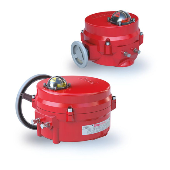
Summary of Contents for Bray SERVO PRO 70 Series
- Page 1 Your Global Flow Control Partner ™ Series 70 SERVO PRO Version 3.0 Operation and Maintenance Manual...
-
Page 3: Table Of Contents
Troubleshooting Chart ........19 FOR MORE INFORMATION ON THIS PRODUCT AND OTHER BRAY PRODUCTS... -
Page 4: Safety Instructions - Definition Of Terms
It cannot take into account every potential occurrence in installation, operation, maintenance and use. If situations transpire that are not documented in sufficient detail, please request the required information from the Bray Distributor or Representative responsible for your area. -
Page 5: Intended Use
The actuator is designed for installation inside maintenance are observed, and the product is used the Bray S70 Electric Actuator, and to position an for its intended purpose, there is normally no danger industrial quarter-turn valve. It must be installed with regard to material damage or personnel health. -
Page 6: Terminal Connections
Series 70 Servo Pro Operation and Maintenance Manual position, which will move the associated control The Servo Pro simultaneously provides a feedback valve to modify the process variable. The process output signal representing the current actuator controller continually calculates and transmits the position. -
Page 7: Configuration Switches
Series 70 Servo Pro Operation and Maintenance Manual Configuration Switches NOTICE Disconnect all electric power to the Servo Pro prior to adjusting configuration switches. Reconnect electric power only after all the configuration switches are in the proper position. The configuration switches are located on the top edge of the Servo Pro Revision F or higher, between the Calibration button and the Status LED. -
Page 8: Configuration Switch Function Description
Servo Pro Revision F or higher are set to the following default positions when shipped NOTICE from the Bray factory: Switch 1 – Off The command signal is considered lost when it is below the low limit of the selected range. -
Page 9: Previous Revisions Of Servo Pro
Series 70 Servo Pro Operation and Maintenance Manual Previous Revisions of Servo Pro There are two very distinct differences between Revision D and F or higher: (a) the Configuration The previous version of Servo Pro (Revision D) has switch arrangement, and (b) the physical layout a different physical layout and configuration switch of the PCB. -
Page 10: Quick Setup Instructions
Sections 2.1, 2.2 and 2.3 when performing the Quick Setup. a. Bray actuators are shipped with the travel switches in the factory default position - close A. Set the Command Signal Input configuration. travel limit set at 0 degrees and the open travel B. - Page 11 Series 70 Servo Pro Operation and Maintenance Manual Non-Metallic Conduit: proper position to match the travel switch factory default (fully close at 0 degrees and Conductor carrying less than 20A = At least 8 in fully open at 90 degrees) Conductor carrying more than 20A up to 100kVA = c.
- Page 12 Series 70 Servo Pro Operation and Maintenance Manual d. Reducing the opening speed of the actuator Appropriately sized surge suppressors should be installed whenever inductive loads such as can allow more precise positioning of the transformers, relays, solenoids, motors, etc. are actuator.
-
Page 13: Calibration Procedure
Series 70 Servo Pro Operation and Maintenance Manual Calibration Procedure Motor Power LEDs The calibration procedure should be run when the There are two Motor Power LEDs. Servo Pro is first commissioned, and anytime that a The Motor Open LED will light green when the Servo subsequent change is made to either the Servo Pro Pro is powering the motor in the open direction. -
Page 14: Status Led Flash Codes
Series 70 Servo Pro Operation and Maintenance Manual Status LED Flash Codes Table 3 shows various diagnostic Flash Codes and their descriptions. If more than one advisory condition or error condition exists, only one Flash Code will appear at a time. The first condition must be corrected before the second (or subsequent) Flash Code will appear. -
Page 15: Hardware Description
Series 70 Servo Pro Operation and Maintenance Manual 5.0 Hardware Description CAUTION The microprocessor-controlled Servo Pro enhances the operation of the S70 actuator by providing full The terminal block connections designed for high positioning control, supplying an actuator position voltage are placed behind a solid line labeled feedback signal, responding to various switch HIGH VOLTAGE on the silk screen. -
Page 16: Output Signal Terminals
Series 70 Servo Pro Operation and Maintenance Manual Refer to the configuration Switch Chart in Section 2.2. CAUTION The potentiometer command signal option is Do not connect any high voltage power to the useful to demonstrate an actuator equipped with output signal terminals as damage could result. -
Page 17: Travel Limit Switch Terminals
Series 70 Servo Pro Operation and Maintenance Manual CAUTION CAUTION Do not connect any high voltage power to the Do not connect any high voltage power to the travel hand-wheel switch terminals as damage could result. limit switch terminals as damage could result. Engaging the handwheel prevents the actuator 5.1.6 Torque Limit Switch Terminals motor from becoming energized, but it does not... -
Page 18: Feedback Potentiometer
Series 70 Servo Pro Operation and Maintenance Manual NOTICE A torque switch that is broken, improperly wired, or missing from the actuator can result in an open contact which will be interpreted by the Servo Pro as the actuator being at its max torque limit. If the optional torque switches are not installed, select Torque... -
Page 19: Control Box Terminal
The right to change or modify product design or product without prior notice is reserved. Patents issued and applied for worldwide. is a registered trademark of Bray International, Inc. | © 2016 Bray International, Inc. All rights reserved. | OM-70-002 Bray ®...


Need help?
Do you have a question about the SERVO PRO 70 Series and is the answer not in the manual?
Questions and answers