Table of Contents
Advertisement
Quick Links
Advertisement
Table of Contents

Subscribe to Our Youtube Channel
Related Manuals for minkaAire BARN H2O


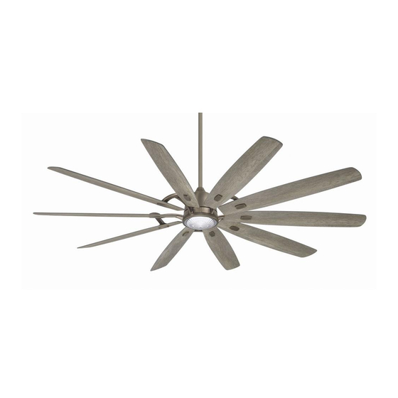
Summary of Contents for minkaAire BARN H2O
- Page 1 BARN H INSTRUCTION MANUAL WARRANTY CERTIFICATE...
- Page 2 ©2021 Minka Lighting Inc. Manual design and all elements of manual design are protected by United States Federal and/or State Law including Patents, Trademark, and/or Copyright Laws.
- Page 3 The Minka-Aire® warranty is for one (1) year from the date of purchase from an authorized Minka-Aire® dealer. This warranty is only valid to the original purchaser or user against all defects in material and workmanship (light bulbs excluded) for one (1) full year. Additionally, Minka-Aire® warrants the motor only for the lifetime of the Minka Aire ceiling fan (excluding wall controls and electrical components), to the original purchaser or user.
- Page 4 Warranty Service Information To obtain warranty service during the warranty period, the purchaser should return the fan with the sales receipt to the original place of purchase. The authorized Minka-Aire® dealer, at its sole discretion, will either repair or replace the fan after verifying the legitimacy of the warranty claim.
-
Page 5: Table Of Contents
CONTENTS SAFETY RULES................... INSTALLING THE LED LIGHT KIT .............. PACKAGE CONTENTS................INSTALLING THE GLASS SHADE ............. INSTALLING THE FAN................OPERATING THE REMOTE CONTROL........... HANGING THE FAN................ENJOY YOUR SMART CEILING FAN............ELECTRICAL CONNECTIONS.............. CARE OF YOUR FAN..................FINISHING THE INSTALLATION............TROUBLESHOOTING................... -
Page 6: Safety Rules
SAFETY RULES 1. Before you begin installing the fan, shut power off at the circuit breaker of the fuse box. 2. Be cautious! Read all instructions and safety information before installing your new fan. Review accompanying assembly diagrams. 3. Make sure that all electrical connections comply with local codes, ordinances, or National Electrical Codes. Hire a qualified electrician or consult a do-it-yourself wiring handbook if you are unfamiliar with installing electrical wiring. - Page 7 NOTE: The important safeguards and instructions appearing in this manual are not meant to cover all possible conditions and situations that may occur. It must be understood that common sense, caution and care are factors which can not be built into this product. These factors must be supplied by the person (s) installing, caring for and operating the unit.
-
Page 8: Package Contents
PACKAGE CONTENTS Unpack your fan and check the contents. You should have the following items: Fan blades (10) 1.5V AAA battery (2) Hanger bracket plate Balancing kit Hanger bracket Canopy Mounting hardware: Canopy cover #14 x 3.5" Wood screws (2 PCs.) Downrod rubber cover Lock washers (2 PCs.) Downrod assembly... -
Page 9: Installing The Fan
INSTALLING THE FAN Tools Required: Phillips screw driver; slotted screw driver; step-ladder; wire cutters; electrical tape. MOUNTING OPTIONS PARALLEL WOOD BRACE CEILING (MIN. 2" THICK) JOIST If there isn't an existing mounting box,then read the following instructions.Shut the power off OUTLET CROSS BRACE at the circuit breaker or fuse box. -
Page 10: Hanging The Fan
HANGING THE FAN WARNING: All of the parts, hardware and components such as Step 3. Secure hanger bracket to hanger bracket plate using the two hex the hanger bracket and hanger ball have been provided for your nuts and washers provided, make sure nuts are securely tighten. (Fig. 7) safety and the proper installation of your new ceiling fan. - Page 11 Step 9. Now lift motor assembly into position and place hanger ball into hanger bracket. Rotate until the check groove has dropped into the registration slot and seats firmly. (Fig. 12) Rod should not rotate if this is done correctly. Step 10.
- Page 12 SAFETY CABLE DOWNROD RUBBER COVER DOWNROD CANOPY CANOPY COVER SAFETY CABLE SET SCREWS COUPLING COVER REGISTRATION SLOT LOCK PIN HITCH PIN Fig. 11 Fig. 12...
-
Page 13: Electrical Connections
ELECTRICAL CONNECTIONS WARNING: To avoid possible electrical shock be sure electricity is turned off at the main fuse or breaker box before wiring. FREQUENCY NOTE: The Aire Control ® 1 2 3 4 5 1 2 3 4 5 System is equipped with a learning frequency function which has 1024 code combinations to prevent potential interference from other remote units. - Page 14 Step 1. Motor to House Supply Wires Electrical Connections: Connect the WHITE wire (Neutral) from the outlet box to the WHITE wire marked "AC in N" from the motor. Connect the BLACK wire (Hot) from the outlet box to the BLACK wire marked "AC in L" from the motor. Secure all wire BLACK (HOT) GREEN OR BARE connections with the plastic wire nuts provided.
-
Page 15: Finishing The Installation
FINISHING THE INSTALLATION OUTLET BOX Step 1. Remove 1 of the 2 screws from the bottom of the hanger bracket and loosen the other one half a turn from the screw head. HANGER BRACKET Step 2. Slide the canopy up towards the hanger bracket and place the key hole on the canopy over the screw on the hanger bracket, turn canopy until it locks in place at the narrow section of the key holes. -
Page 16: Attaching The Fan Blades
ATTACHING THE FAN BLADES BLADE MOUNTING SCREWS Step 1. Attach the blade to the blade holders and blade medallions using the blade WITH LOCK WASHERS mounting screws with lock washers (3/16" x 15mm) as shown in Figure 16. Start a screw into the blade holder, do not tighten. -
Page 17: Installing The Mounting Plate
INSTALLING THE MOUNTING PLATE Step 1. Remove 1 of 3 screws from the mounting ring and loosen the other 2 screws. (Do not remove) Step 2. Place the key holes from the mounting plate over the 2 screws previously loosened from the mounting ring, turn mounting plate until it locks in place at the narrow section of the key holes. -
Page 18: Installing The Led Light Kit
INSTALLING THE LED LIGHT KIT NOTE: Before starting installation, make sure power is turned off at the circuit breaker. CAUTION: The light source is designed for this specific application and can overheat if serviced by untrained personnel. If any servicing is required, the product should be returned to an authorized service facility for examination or repair. -
Page 19: Installing The Glass Shade
INSTALLING THE GLASS SHADE Raise glass shade up against LED light kit and secure it to the fan by turning the glass shade clockwise until snug. DO NOT OVERTIGHTEN. (Fig. 19) GLASS SHADE Fig. 19... -
Page 20: Operating The Remote Control
OPERATING THE REMOTE CONTROL Remote Control only: Install two AAA 1.5 volt batteries (included). To prevent damage to transmitter remove the battery if not used for long periods of time. IMPORTANT: THIS REMOTE CONTROL & DC FAN MOTOR ARE DESIGNED TO PERFORM A ONE TIME SELF CALIBRATION TEST. THIS TEST WILL BEGIN ONCE A NEW CODE HAS BEEN SET, AND WILL LAST APPROXIMATELY ONE MINUTES. - Page 21 NOTE: The auto learning function will only mandate within 60 seconds 1. Lock position: The DC motor has a built-in safety against obstruction when turning the fan’ s AC power ON. during operation. The motor will get locked operation and disconnect power after 30 seconds if interruption occurs.
- Page 22 Speed settings for warm or cold weather depend on factors such as room size, ceiling height and number of fans. NOTE: To change the direction of the rotation of the blades the fan must be in operation mode. Warm Weather (forward) A DOWNWARD airflow creates a cooling effect as shown in Figure 20.
-
Page 23: Enjoy Your Smart Ceiling Fan
ENJOY YOUR SMART CEILING FAN NOTE: Before moving on to learning about your new smart ceiling fan, please be sure to test all your fans functionalities using your remote control first. To enjoy all the potential of your new ceiling fan. You’ll need to dowload the BOND HOME app. -
Page 24: Care Of Your Fan
CARE OF YOUR FAN Here are some suggestions to help maintain your fan. 4. Use a lint free lightly damp cloth or duster to remove dust from the blades. 1. Because of the fan's natural movement some connections may become loose. Check the support connections, brackets and blade 5. -
Page 25: Troubleshooting
TROUBLESHOOTING SYMPTOM SYMPTOM Fan will not start Fan Sounds Noisy SOLUTION SOLUTION Check to make sure the wall switch is turned on. Allow a 24-hour "break in" period. Most noises associated with a new fan will go away during this time. Check circuit fuses or breakers. - Page 26 SYMPTOM SYMPTOM Fan Wobble Does not connect to WiFi home network. SOLUTION SOLUTION NOTE: All blade sets are grouped by weight. Because wood and plastic If you are having trouble completing the Bond Home connection with your ceiling fan, adjustments to your router settings may be blades vary in density, the fan may wobble even though blades are matched.
- Page 27 SYMPTOM Within 60 seconds of turning the Fan's AC power ON. Press the transmitter's "Stop" button and hold the "Stop" button for 10 seconds. Fans/Light Turn On and Off Unexpectedly SOLUTION Once the receiver has detected the set frequency, the down light of This is caused by interference, Please see "Frequency interference"...
-
Page 28: Specifications
SPECIFICATIONS Fan Size Speed Volts Amps Watts N.W. G.W. C.F. These are typical readings. Your actual fan may vary. They do not include amps and wattage used by the light(s). 0.08 4.19 84" 19.6 22.0 4.486' High 0.65 48.48... - Page 29 PERFORMANCE AND ENERGY INFORMATION FAN SPEED AIRFLOW POWER USE AIRFLOW EFFICIENCY (CFM)* (Watts) (CFM/Watt) 4,550 4.19 1,086 High 12,402 48.48 Estimated Ceiling fan airflow is measured in cubic feet per minute (CFM). Airflow Yearly Energy Cost Power use is measured in watts. To maximize energy savings: 8,721 •...
Need help?
Do you have a question about the BARN H2O and is the answer not in the manual?
Questions and answers