Table of Contents
Advertisement
Quick Links
No. CP-UM-1218E
RA890G
PROTECTORELAY
Burner Controller
User's Manual
Thank you for purchasing the RA890G
PROTECTORELAY Burner Controller.
This manual contains information for ensur-
ing the correct use of the RA890G. It also
provides necessary information for installa-
tion, maintenance, and troubleshooting.
This manual should be read by those who
design and maintain equipment that uses
the RA890G. Be sure to keep this manual
nearby for handy reference.
Advertisement
Table of Contents

Related Manuals for Azbil RA890G


Summary of Contents for Azbil RA890G
- Page 1 Thank you for purchasing the RA890G PROTECTORELAY Burner Controller. This manual contains information for ensur- ing the correct use of the RA890G. It also provides necessary information for installa- tion, maintenance, and troubleshooting. This manual should be read by those who design and maintain equipment that uses the RA890G.
- Page 2 If you should find an error or omission, please contact the azbil Group. In no event is Azbil Corporation liable to anyone for any indirect, special or consequential damages as a result of using this product. © 1984-2013 Azbil Corporation All Rights Reserved.
- Page 3 Be sure to follow the indicated instructions. Handling Precautions: Handling Precautions indicate items that the user should pay attention to when handling the RA890G. Notes indicate information that might benefit the user. Note: This indicates the item or page that the user is requested to refer to.
- Page 4 Safety Precautions Safety precautions are intended to ensure the safe and correct use of this product, to prevent injury to the operator and others, and to prevent damage to property. Be sure to observe these safety precautions. Please make sure you under- stand the safety guidelines before reading the rest of this manual.
- Page 5 Do not touch this device's internal relay. Doing so might damage the relay or cause this device and/ or the combustion equipment to malfunction. CAUTION Use the RA890G for the oil-fired or gas-fired combustion equipment up to approx. 700 kW in com- bustion rate. Do not install where exposed to any of the following: •...
- Page 6 CAUTION Always connect the power supply last. Otherwise, touching a terminal accidentally could result in electric shock or damage. Always supply electric power at the voltage and frequency stated on the model label of this device. In keeping with technical standards for electrical equipment, the burner body must have an earth ground connection with a resistance of less than 100 Ω.
-
Page 7: Table Of Contents
. . . . . . . . . . . . . . . . . . . . . . . . . . . . . . . . .5 Mounting the RA890G onto the subbase ■... -
Page 9: Chapter 1. Overview
• The RA890G is operated after mounted directly onto the Q270A subbase. System configuration ■ In terms of the overall system, the RA890G serves as the ignition controller and the flame monitoring device. It is used as shown in the diagram below. High limit controller... -
Page 10: Security Function And Precautions For Facility Instrumentation
• The RA890G operates each device according to the predetermined sequence and timing. (3) Safe startup • At every startup signal, the RA890G checks for false flame in the flame detec- tor and flame detection circuit. • If a problem is detected, the RA890G does not start the burner. -
Page 11: Names Of Parts
Chapter 1. OVERVIEW Names of parts ■ Terminal block Flame relay Load relay (2K) (1K) Safety switch Q270A1024 Flame current Subbase test jack (sold separately) Transformer 2 Mounting base (TR2) Transformer 1 (TR1) Safety switch reset button Cover Cover retaining screw... -
Page 12: Chapter 2. Mounting
Chapter 2. MOUNTING Handling Precautions • Installation, wiring, inspection, adjustment, etc. should be carried out by a trained and experienced technician who has knowledge and technical skills related to combustion equipment and flame safeguard control devices. Mounting the subbase ■ CAUTION Do not install where exposed to any of the following: •... -
Page 13: Mounting The Ra890G Onto The Subbase
(1) Loosen the cover retaining screws and remove the cover from the RA890G. (2) Set the position of the RA890G mounting base to that of the subbase. (3) Tighten the terminal screws (10 pcs) of the RA890G securely in the individual terminal thread holes in the subbase using 1 N·m tightening torque. -
Page 14: Chapter 3. Wiring
Chapter 3. WIRING WARNING The RA890G performs recycle operation during flame failure. Therefore, when it is to be used together with a gas-fired combustion system, operate it in non-recycle sequence by using an on- delay timer. Wire terminals 1 and 2 so that they receive power continuously whenever the power switch is turned on. -
Page 15: Non-Recycling Gas-Fired Combustion
Wiring diagram ● Power supply Power supply Blower on-o circuit / prepurge circuit Thermostat* (for power supply) Limit/interlock circuit (limit switch, interlock switch) RA890G AUD100 Series Blue Flame White detection Burner start contacts Main valve 1... - Page 16 • Voltage to terminals 3, 4, and 5 stops, and all loads stop operation. • The RA890G returns to the initial state and is ready for the next re- quest from the thermostat (for low voltage). Burner start contacts ON Thermostat (for low voltage) ON Start check (appox.
- Page 17 Even if the on-delay timer is set to more than 15 s, the ignition transformer stops after the lockout time of 15 s. Ignition failure ● Input status RA890G operation Output status Power ON • Power is supplied to terminals 1 and 2, and voltage is applied to transformer TR2.
- Page 18 Chapter 3 WIRING Flame failure during combustion ● Input status RA890G operation Output status Power ON • Power is supplied to terminals 1 and 2, and voltage is applied to transformer TR2. Blower ON • The blower turns on. When the prepurge ends, the prepurge com- pletion signal is generated to make the next process possible.
- Page 19 On-delay time Lockout timing (appox. 15s) False flame signal at startup ● Input status RA890G operation Output status Power ON • Power is supplied to terminals 1 and 2, and voltage is applied to transformer TR2. False flame signal is •...
-
Page 20: Recycling Oil-Fired Combustion (2-Stage Combustion)
Relay 2K has contacts 2K1 to 2K4 for the flame detector. Wiring diagram ● Power supply Power supply Blower on-o circuit / Prepurge circuit Thermostat* (for power supply) Limit/interlock circuit (limit switch, interlock switch) RA890G AUD100 Series Blue Flame White detection Burner start contacts Secondary... - Page 21 • Voltage to terminals 3, 4, and 5 stops, and all loads stop operation. • The RA890G returns to its initial status and is ready for the next re- quest from the thermostat (for low voltage). Burner start contacts ON Thermostat (for low voltage) ON Start check (appox.
- Page 22 Before restarting, be sure to do a prepurge. Failure to discharge unburned gas that has accumu- lated in the flue and combustion chamber may result in an explosion. Ignition failure ● Input status RA890G operation Output status Power ON • Power is supplied to terminals 1 and 2, and voltage is applied to transformer TR2.
- Page 23 Chapter 3 WIRING Flame failure during RUN ● Input status RA890G operation Output status Power ON • Power is supplied to terminals 1 and 2, and voltage is applied to transformer TR2. Blower ON • The blower turns on. When the prepurge ends, the prepurge com- pletion signal is generated to make the next process possible.
- Page 24 Chapter 3 WIRING • When the system restarts Burner start contacts ON Start check (appox. 3s) Thermostat (for low voltage) ON Flame detection Blower ON Flame Flame response (appox. 3s) failure Flame detection Power ON Limit, Interlock circuit Blower on-o circuit Prepurge Prepurge completion signal Burner start contacts...
- Page 25 Chapter 3 WIRING False flame signal at the start of operation ● Input status RA890G operation Output status Power ON • Power is supplied to terminals 1 and 2, and voltage is applied to transformer TR2. False flame sig- •...
-
Page 26: Wiring The Solenoid Valve
Correct connection ● High voltage side (H) 100V Power RA890G Ground side (G) (Ground fault) Valve (closed) Fuel Ground current will not flow to the solenoid valve with the valve wired as shown in the figure above, even if faulty insulation on the voltage side (H) causes a ground fault. -
Page 27: Chapter 4. Inspection And Adjustment
Chapter 4. INSPECTION AND ADJUSTMENT Handling Precautions • A trained and experienced technician who has knowledge and technical skills related to combustion equipment and flame safeguard control devices should carry out inspection, adjustment, etc. WARNING Do not allow the pilot or main burner ignition trial time to exceed the specifications of the burner or equipment manufacturer. - Page 28 (5) Check if the burner has been adjusted properly. (6) Check the exhaust mechanism in the flue. (7) Press the green pushbutton at the front of the RA890G to reset the safety switch. Wiring check of the AUD 100 Series Advanced Ultraviolet Flame Detector ●...
- Page 29 15 µA, and insert the current measurement plug of an analog flame meter FSP136A100 into the flame current test jack of the RA890G. Then, operate the burner and read the flame current from the analog flame meter. If the flame cur- rent is abnormal, see the users' manual for the flame detector.
-
Page 30: Ignition Spark Response Test
Chapter 4 INSPECTION AND ADJUSTMENT Ignition spark response test ■ CAUTION Make sure that the flame detector does not detect the ignition spark. If the flame detector detects the spark, change the position of the detector or the ignition electrode. Adjust the flame detector so that it detects only the ultraviolet rays of the burner flame. -
Page 31: Pilot Turndown Test
Chapter 4 INSPECTION AND ADJUSTMENT Pilot turndown test ■ WARNING Do not allow the pilot or main burner ignition trial time to exceed the specifications of the burner or equipment manufacturer. If they do, fuel may accumulate in the combustion chamber and form an explosive air-fuel mixture, resulting in a serious explosion hazard. -
Page 32: Safety Shutdown Checks
Chapter 4 INSPECTION AND ADJUSTMENT (9) While changing the gas pressure to minimum and maximum values, repeat ignition to the main burner 5 or 6 times. Then, check if ignition is performed smoothly within 1 second every time. (10) If the main burner cannot be lighted, it is necessary to enlarge the size of the pilot flame. -
Page 33: Chapter 5. Maintenance
Chapter 5. MAINTENANCE Handling Precautions • The maintenance, inspection and adjustment shall be made by trained, expe- rienced flame safeguard control technicians. WARNING Before wiring, mounting, or removing this device, be sure to turn the power on and then immedi- ately off. -
Page 34: Troubleshooting
Troubleshooting ■ WARNING Use utmost care while troubleshooting the RA890G since the line voltage can be present on most terminals when power is on. To prevent electric shock, turn the power off and discharge terminals F and G before removing this device from the subbase. - Page 35 ON the controller and check the voltage between the terminals 2 and 6 again. Replace the RA890G if the load relay is not excited still, although the rated voltage is obtained there. If a low voltage thermostat is used, proceed to step 6.
- Page 36 (1) When the normal voltage is obtained, check the main fuel valve and valve circuit. (2) If the normal voltage is not obtained, replace the RA890G. Step 11. Check if sparks are cut off when the flame relay is excited, if the ignition trans- former is connected to the terminal 4.
-
Page 37: Chapter 6. Specifications
Chapter 6. SPECIFICATIONS Specifications ■ Item Specifications Model number RA890G117_2 RA890G1278_2 Rated voltage 100 Vac 208 Vac Allowable voltage 85 to 110 % of rated voltage Rated frequency 50/60 Hz Power consumption 10.5 W (18 VA) max. for 50 Hz 9.5 W (14 VA) max. -
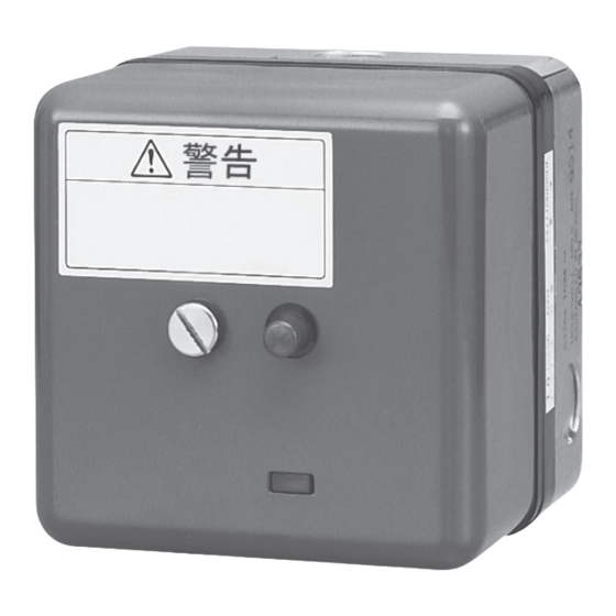
Page 38: External Dimensions
Chapter 6 SPECIFICATIONS External dimensions ■ Main device ● Terminal screws (#6-32UNC) Warning label Warning label Safety switch reset button Faston tab 250 series (Receptacle and insulating sleeve, 3 pcs each attached) 50.5 Cover retaining screw Subbase (Q270A1024) Cover Q270A102A sub base (sold separately) ●... - Page 39 Revision History of CP-UM-1218E Printed Edn. Revised pages Description Mar. 1984 Nov. 2008 Overall revision. 11th ed = 16th Jp ed. Overall revision due to discontinuation of 123514B flame simulator and Nov. 2011 introduction of AUD100 series advanced ultraviolet flame detector Apr.
- Page 40 (5) Failure that the state of the art at the time of Azbil Corporation's shipment did not allow us to predict; or (6) Failure that arose from any reason not attributable to Azbil Corporation, including, without limitation, acts of God, disasters, and actions taken by a third party.
- Page 41 Azbil Corporation's products every 5 to 10 years unless otherwise specified in specifications or instruction manuals.
- Page 42 Specifications are subject to change without notice. (09) 1-12-2 Kawana, Fujisawa Kanagawa 251-8522 Japan URL : http://www.azbil.com 14th edition: Apr. 2013 ( F )
Need help?
Do you have a question about the RA890G and is the answer not in the manual?
Questions and answers