Table of Contents
Advertisement
Quick Links
IP
65/67
Input AC 380-480V
G
ENERAL DESCRIPTION
The FPS300 is an industrial grade power supply for the
1-phase mains system, it is incorporated into a rugged
wall-mount housing with an
protection.
It provides two to four stabilized outputs that are
galvanically separated from the input. The negative
potential of the outputs is permanently connected to
PE within the unit.
The most outstanding features of the FPS series are the
compact size, the wide operating temperature range,
the extremely low input inrush current and the very
high efficiencies, which are achieved through various
design technologies. Large output capacitors can
absorb and store regenerative energy from breaking
motors.
Various connector options support the different needs
of individual applications. Please contact PULS for
possible options. High immunity to transients and
power surges as well as low electromagnetic emissions
and an international approval package makes the use
in nearly every application possible.
O
RDER NUMBERS
Description:
Order Number
FPS300.245-034-105*
FPS300.245-047-103
FPS300.245-055-109
Accessories:
Related Products
*For DIN rail mounting PSU: (Order Number)D
e.g. FP300.245-034-105D
All parameters are specified at 24V, 12.5A, 230Vac, 25°C ambient and after a 5 minutes run-in time unless otherwise noted.
Feb. 2022 / Rev. 0.1 DS-FPS300-EN
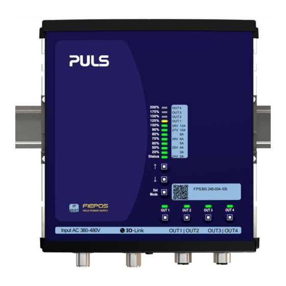
OUT 4
OUT 3
OUT 2
OUT 1
28V
12A
27V
10A
8A
26V
6A
5A
25V
4A
3A
24V
2A
FPS300.245-034-105
OUT1 | OUT2
OUT3 | OUT4
IP65/67 degree of
Power supply FPS300
Input
Output
M12-S
M12-L
7/8" 3 pin
7/8" 4 pin
7/8" 3 pin
7/8" 5 pin
Chapter 21
Chapter 22
P
OWER SUPPLY
•
IP 65/67 Degree of protection
•
600 W
5 s
peak
•
1AC 100-240 V wide-range input
•
4 switchable outputs
•
Outputs for actors and sensors separately protected
•
95.7 % full load and excellent partial load efficiencies
•
DIN rail mounting possible, option "D"
•
Output connected to PE (PELV)
•
Version without connection to PE on request
•
Large output capacitors
•
Not potted
•
Negligible low input inrush current surge
•
Full power between -25 °C and +55 °C
•
IO-Link
•
3 years warranty
S
HORT-FORM DATA
Output voltage
DC 24 V
Adjustment range
24-28 V
Output power
Continuous:
360 / 300 / 150 W +45 / +55 / +70 °C
Short term up to 5 s
600 / 300 W
Derate linearly
+55 °C to +70 °C
Number of output
4
Output currents
Settable per output; up to 12 A
Input voltage AC
1AC 100-240 V
Input voltage DC
DC
Power factor
0.99 / 0.97
AC Inrush current
2.6 / 6A
Efficiency
94.3 / 95.7 %
Losses
18.1 / 13.5W
Hold-up time
44 / 44 ms
Temperature range
-25 °C to +70 °C
Size (wxhxd)
181x183x59 mm Without connectors
Weight
1200 g / 2.7 lb
*)
For DC supply voltages above 150 Vdc an external fuse is
required.
M
AJOR APPROVALS AND CONFORMITY
For details or a complete approval list, see chapter 21.
IEC 62368-1
IEC 61010-2-201
www.pulspower.com
FPS300.245-034-105
FPS300.245-047-103
FPS300.245-055-109
100-240Vac 24V 300W
Nominal
Factory setting 24.5 V
Up to:
+55 / +70 °C
-15 / +10%
110-300V*)
±20%
At 120 / 230 Vac
At 120 / 230 Vac
peak
At 120 / 230 Vac
At 120 / 230 Vac
At 120 / 230 Vac
1 / 45
Advertisement
Table of Contents

Related Manuals for Puls Fiepos FPS300.245-034-105


Summary of Contents for Puls Fiepos FPS300.245-034-105
- Page 1 Various connector options support the different needs Losses 18.1 / 13.5W At 120 / 230 Vac of individual applications. Please contact PULS for Hold-up time 44 / 44 ms At 120 / 230 Vac possible options. High immunity to transients and Temperature range -25 °C to +70 °C...
- Page 2 FPS300.245-034-105 FPS300.245-047-103 FPS300.245-055-109 NDEX INDEX .................. 2 Approvals and Fulfilled Standards ......31 Intended Use .............. 4 Regulatory Compliance ........... 31 Installation Instructions ..........4 Accessories ............... 32 AC-Input ..............5 21.1. DIN RAIL Mounting KIT: ZM.FPDRA-11 ..32 21.2. Mounting Braket: ZM.FPMBA-11....
- Page 3 FPS300.245-034-105 FPS300.245-047-103 FPS300.245-055-109 OMENCLATURE Detail Description 380-480 V 3 Phase IP54-67 Power Supply 100-240 V 1 Phase IP54-67 Power Supply 200-240 V 1 Phase IP54-67 Power Supply Highline Input Voltage 300 W Power Class 500 W Power Class 241 / 481 Standard Power Supply with Output Voltage 24-28 V / 48-52 V Setting and LED Bar 242 / 482 Basic Power Supply without Voltage Setting and LED-Bar.
-
Page 4: Intended Use
FPS300.245-034-105 FPS300.245-047-103 FPS300.245-055-109 Intended Use This device is designed for indoor use and is intended for commercial applications, such as in industrial control, process control, monitoring and measurement equipment. Do not use this device in equipment where malfunction may cause severe personal injury or threaten human life. If this device is used in a manner outside of its specification, the protection provided by the device may be impaired. - Page 5 FPS300.245-034-105 FPS300.245-047-103 FPS300.245-055-109 AC-Input The device is suitable to be supplied from TN, TT or IT mains networks. For more details, please review chapter 2. AC input voltage rated range nom. AC 100-240 V AC input operating range 85-264 Vac Continuous operation 264-300 Vac For maximal 500ms...
-
Page 6: Input Inrush Current
FPS300.245-034-105 FPS300.245-047-103 FPS300.245-055-109 DC-Input The device is suitable to be supplied from a DC input voltage. input*) nom. DC 110-300 ±20 % DC input range min. 88 Vdc max. 180 Vdc DC input current typ. 2.90 A At 110 Vdc, at 24 V, 300 W typ. - Page 7 FPS300.245-034-105 FPS300.245-047-103 FPS300.245-055-109 Output The outputs provide a (PELV/ES1) rated voltage, which is galvanically isolated from the input voltage. The negative potential of the outputs is permanently connected to PE within the unit. Do not connect any output to PE (Ground). The device is designed to supply any kind of loads, including capacitive and inductive loads.
- Page 8 FPS300.245-034-105 FPS300.245-047-103 FPS300.245-055-109 Fig. 6-1: Sequential start of the outputs Fig. 6-2: Tripping of the channel with the lowest priority when the power budget is exceeded Fig. 6-3: Trip curve diagram All parameters are specified at 24 V, 12.5 A, 230 Vac, 25 °C ambient and after a 5 minutes run-in time unless otherwise noted. Apr.
-
Page 9: Hold-Up Time
FPS300.245-034-105 FPS300.245-047-103 FPS300.245-055-109 Hold-up Time The hold-up time is the time during which a power supply’s output voltage remains within specification following the loss of input power. The hold-up time is output load dependent. At no load, the hold-up time can be up to several seconds. The status LED is also on during this time. -
Page 10: Io-Link Interface
To operate the IO-Link interface it is required to install/upload the IODD-File (IO-Link Device Description) into the connected IO-Link master. The most recent IODD file can be found on the PULS website (www.pulspower.com) in the download section of the individual product page. The device can also be accessed via IO-Link, if the power supply is not connected to AC- mains and in a switched off mode. - Page 11 FPS300.245-034-105 FPS300.245-047-103 FPS300.245-055-109 Parameter The parameter values can be accessed to read out additional data (e.g. current output voltage, temperatures etc Parameter read read out value range Description Output Voltage Setpoint 24.0-28.0 V Output Voltage Setpoint Pre-Setting- 24.5 V Standby 0 - unit is operating PSU can be switched into standby, where all outputs 1 - unit in standby...
- Page 12 FPS300.245-034-105 FPS300.245-047-103 FPS300.245-055-109 Parameter read read out value range Description Actual output current 0-68 A Actual average total output current E-Fuse current 0-15 A Actual average E-Fuse output current for each E-Fuse channel 1 to channel 4 channel E-Fuse output status bit 0 - Ch1 Actual state of E-Fuse output channels bit 1 - Ch2...
-
Page 13: Device Status
FPS300.245-034-105 FPS300.245-047-103 FPS300.245-055-109 Counter E-Fuse Number of Startups 0-150000 Counts the number of startups on each E-Fuse channel 1 to channel 4 channel over the whole lifetime. E-Fuse Number of 0-150000 Number of Overcurrents on each E-Fuse channel over Overcurrents channel 1 to the whole lifetime. -
Page 14: Event Data
FPS300.245-034-105 FPS300.245-047-103 FPS300.245-055-109 Event Data This set of data is on read only. Event data reports on parameter errors and warns of device failures of the power supply to the IO-Link master. It is triggered when certain critical conditions or control settings are exceeded. Typical events are e.g. ambient temperature too hot, high input voltage, etc. -
Page 15: Process Data
FPS300.245-034-105 FPS300.245-047-103 FPS300.245-055-109 Process Data This set of data is on read only. Process data reports on the current state and conditions of the power supply to the IO-Link master. Typical process data are, e.g. actual output voltage of each output channel, internal temperatures, tripping status reports, etc. -
Page 16: Efficiency And Power Losses
FPS300.245-034-105 FPS300.245-047-103 FPS300.245-055-109 Efficiency and Power Losses AC 100 V AC 120 V AC 230V Efficiency typ. 93.6 % 94.3 % 95.7 % At 24 V, 300 W Average typ. 92.9 % 93.5 % 94.6 % 25 % at 80 W, 25 % at 150 W, 25 % at 220 W, 25 % at efficiency*) 300 W Power losses... -
Page 17: Lifetime Expectancy
FPS300.245-034-105 FPS300.245-047-103 FPS300.245-055-109 Lifetime Expectancy The Lifetime expectancy shown in the table indicates the minimum operating hours (service life) and is determined by the lifetime expectancy of the built-in electrolytic capacitors. Lifetime expectancy is specified in operational hours and is calculated according to the capacitor’s manufacturer specification. -
Page 18: Functional Diagram
FPS300.245-034-105 FPS300.245-047-103 FPS300.245-055-109 Functional Diagram Fig. 12-1: Functional Diagram FPS300.245-034-105 Fig. 12-2: Functional Diagram FPS300.245-047-103 All parameters are specified at 24 V, 12.5 A, 230 Vac, 25 °C ambient and after a 5 minutes run-in time unless otherwise noted. Apr. 2022 / Rev. 0.2 FPS300.245-EN www.pulspower.com 18 / 45... - Page 19 FPS300.245-034-105 FPS300.245-047-103 FPS300.245-055-109 Fig. 12-3: Functional Diagram FPS300.245-055-109 All parameters are specified at 24 V, 12.5 A, 230 Vac, 25 °C ambient and after a 5 minutes run-in time unless otherwise noted. Apr. 2022 / Rev. 0.2 FPS300.245-EN www.pulspower.com 19 / 45...
- Page 20 FPS300.245-034-105 FPS300.245-047-103 FPS300.245-055-109 Dimensions and Connector Variants FPS300.245-034-105 Width 181 mm / 7.11'' Housing body material Aluminium alloy Height 183 mm / 7.2'' Housing cover material Hi-grade polycarbonate Depth 59 mm / 2.32'' Installation clearances See chapter 2 Weight 1200 g / 2.7lb Mating connectors See chapter 21.3 Input connector on power supply (X1):...
- Page 21 FPS300.245-034-105 FPS300.245-047-103 FPS300.245-055-109 FPS300.245-047-103 Width 181 mm / 7.11'' Housing body material Aluminium alloy Height 183 mm / 7.2'' Housing cover material Hi-grade polycarbonate Depth 59 mm / 2.32'' Installation clearances See chapter 2 Weight 1200 g / 2.7lb Mating connectors See chapter 21.3 Input connector on power supply (X1): 7/8”...
- Page 22 FPS300.245-034-105 FPS300.245-047-103 FPS300.245-055-109 FPS300.245-055-109 Width 181 mm / 7.11'' Housing body material Aluminium alloy Height 183 mm / 7.2'' Housing cover material Hi-grade polycarbonate Depth 59 mm / 2.32'' Installation clearances See chapter 2 Weight 1200 g / 2.7lb Mating connectors See chapter 21.3 Input connector on power supply (X1): 7/8”...
-
Page 23: User Interface
FPS300.245-034-105 FPS300.245-047-103 FPS300.245-055-109 User Interface Input Connector Output Connectors IO-Link Connector Status LED LED Bar Set Mode and Up and Down Button Output LEDs ON/OFF & Reset Buttons Overview LED Bar (E) The LED Bar is a multifunctional displaying tool. The main function is to monitor the sum of all outputs (percentages scale). It also can display the output voltage (voltage scale) and output current (ampere scale) for the individual outputs. - Page 24 FPS300.245-034-105 FPS300.245-047-103 FPS300.245-055-109 Set Tripping Current To set a new tripping current: Press Set Mode for 3 s. After all LEDs light up once, the LED now displays the set voltage. Press Set Mode to select the right output to change the tripping current. The orange LED will indicate which output is selected.
- Page 25 FPS300.245-034-105 FPS300.245-047-103 FPS300.245-055-109 Channel LED Signaling Overview Below is an overview of the output LED signaling. Output is switched OFF by ON/OFF or PSU is not powered (s. Status LED). Green: Default Output is switched on by ON/OFF. Flashes green: Power budget tripped (slow rate: 250 ms ON / 250 ms OFF) Low priority outputs are tripped.
- Page 26 FPS300.245-034-105 FPS300.245-047-103 FPS300.245-055-109 The EMC behavior of the device is designed for applications in industrial environment as well as in residential, commercial and light industry environments. The device is investigated according to EN 61000-6-1, EN 61000-6-2, EN 61000-6-3, EN 61000-6-4, EN 61000-3-2 and EN 61000-3-3.
- Page 27 FPS300.245-034-105 FPS300.245-047-103 FPS300.245-055-109 EMC Emission Conducted emission AC input lines EN 55011, EN 55015, EN 55032, Class B FCC Part 15, CISPR 11, CISPR 32 Conducted emission DC output lines IEC/CISPR 16-1-2, IEC/CISPR 16-2-1 Conducted emission IO-Link output Radiated emission EN 55032 / EN 55011 Class B Harmonics...
- Page 28 FPS300.245-034-105 FPS300.245-047-103 FPS300.245-055-109 Environment Operational temperature -25 °C to +70 °C (-13 °F to 158 °F) Operational temperature is the same as the ambient or surrounding temperature and is defined as the air temperature 2cm below the unit. Storage temperature -40 °C to +85 °C (-40 °F to 185 °F) For storage and transportation Output derating...
-
Page 29: Safety And Protection Features
FPS300.245-034-105 FPS300.245-047-103 FPS300.245-055-109 Safety and Protection Features Isolation resistance min. 500 MOhm At delivered condition between input and output, measured with 500 Vdc min. 500 MOhm At delivered condition between input and PE, measured with 500 Vdc PE resistance max. 0.1 Ohm Resistance between PE terminal and the housing Input/Output separation... -
Page 30: Dielectric Strength
FPS300.245-034-105 FPS300.245-047-103 FPS300.245-055-109 Dielectric Strength The negative terminal of the outputs is permanently connected to PE within the unit. The output is insulated from the input by a double or reinforced insulation. Type and routine tests are conducted by the manufacturer. Field tests may be conducted in the field using the appropriate test equipment which applies the voltage with a slow ramp (2s up and 2s down). -
Page 31: Regulatory Compliance
FPS300.245-034-105 FPS300.245-047-103 FPS300.245-055-109 Approvals and Fulfilled Standards IEC 62368 CB Scheme Certificate IEC 62368-1 - Audio/video, information and communication CB Report technology equipment - Safety requirements Output safety level: ES1 IEC 61010 CB Scheme Certificate IEC 61010-2-201 - Electrical Equipment for Measurement, Control and Laboratory Use - Particular requirements for control equipment IEC 60950 Manufacturers Declaration... - Page 32 FPS300.245-034-105 FPS300.245-047-103 FPS300.245-055-109 Accessories 21.1. DIN RAIL Mounting KIT: ZM.FPDRA-11 In addition to screw mounting FIEPOS can easily be attached to a DIN rail using the ZM.FPDRA-11 DIN rail mounting kit. • DIN-Rail not included • DIN-Fixture pre-assembled 21.2. Mounting Braket: ZM.FPMBA-11 In addition to screw mounting FIEPOS can easily be attached to a mounting bracket the ZM.FPMBA-11.
- Page 33 FPS300.245-055-109 21.3. Connectors FIEPOS features a large number of different connectors. Mating connectors can be ordered at PULS from stock in order to supply customers quickly during the design-in phase. For a higher demand or other connector options go to HARTING-PULS-cabling.
-
Page 34: Related Products
The FIEPOS product family includes various devices with different technical parameters and features. The following page provides a general overview of the available solutions. Please also get in touch with your PULS contact person, for more detailed application advice and technical information. -
Page 35: External Input Protection
FPS300.245-034-105 FPS300.245-047-103 FPS300.245-055-109 Application Notes 23.1. Repetitive Pulse Loading Typically, a load current is not constant and varies over time. This power supply is designed to support loads with a higher short-term power demand (BonusPower). The short-term duration is hardware controlled by an output power manager and is available on a repeated basis. -
Page 36: Mounting Orientations
FPS300.245-034-105 FPS300.245-047-103 FPS300.245-055-109 23.5. Mounting Orientations The device can be mounted in various mounting orientations. The listed lifetime and MTBF values from this datasheet apply only for the standard mounting orientation. The following curves give an indication for allowed output power in different mounting orientations for altitudes up to 2000 m (6560 ft). - Page 37 FPS300.245-034-105 FPS300.245-047-103 FPS500.245-055-109 IO-Link Data Types and Description 24.1. Cyclic Data The first dataset is called process data and refers to data that is periodically sent to the IO-Link master. The data is updated and communicated every 2ms. All other data in the power supply itself is generated every 50ms and stored in the IO-Link registers.
- Page 38 FPS300.245-034-105 FPS300.245-047-103 FPS500.245-055-109 Octet Subindex Bit offset 119-112 111-104 103-96 95-88 87-80 79-72 71-64 63-56 55-48 47-40 39-32 31-24 Octet 12 Subindex Bit offset Octet13 Subindex Bit offset Octet14 Subindex Bit offset All parameters are specified at 24 V, 20 A, 400 Vac, 25 °C ambient and after a 5 minutes run-in time unless otherwise noted. Apr.
- Page 39 FPS300.245-034-105 FPS300.245-047-103 FPS500.245-055-109 24.2. Acyclic data The parameter values can be accessed to read out additional data (e.g. current output voltage, temperatures etc.), but in addition some of these values can also be written by the user to configure the power supply (e.g. output voltage and remote on/off). Parameter Para.
- Page 40 FPS300.245-034-105 FPS300.245-047-103 FPS500.245-055-109 Parameter Para. Sub- Data Read [R] Description Index index offset type length Write [W] PSU events uint16 dynamic Output-OK bool bit 0…Output Voltage >90% of adjusted output voltage DC-Warning bool bit 1… Output voltage dips more than 10% below adjusted output voltage Bonus Power bool bit 2…...
- Page 41 FPS300.245-034-105 FPS300.245-047-103 FPS500.245-055-109 Parameter Para. Sub- Data Data Resolution Default Read [R] Allowed values Description Index index type offset Format values Write [W] Temperature secondary inside 69 int16 15-0 Q9.7 °C/bit -5120…32640 Temperature secondary inside PSU -40 .. 150°C Max. temperature secondary Maximum temperature secondary inside PSU -40 ..
- Page 42 FPS300.245-034-105 FPS300.245-047-103 FPS500.245-055-109 Parameter Para. Sub- Data Data Resolution Default Read [R] Allowed values Description Index index type offset Format values Write [W] 0 … “<=10%” 1 … “>10%” Remaining Endurance LED uint8 2 … “>=25%” Dynamic coded 3 … “>=50%” 4 …...
- Page 43 FPS300.245-034-105 FPS300.245-047-103 FPS500.245-055-109 Counter Parameter Para. Sub- Data type Data Resolution Default Read [R] Allowed values Description Index index offset Format value Write [W] E-Fuse Number of Startups all CHs uint32 array 127-0 0…150000 Number of Startups all Channels E-Fuse Number of Startups CH1 uint32 127-96 0…150000...
- Page 44 FPS300.245-034-105 FPS300.245-047-103 FPS500.245-055-109 Device Status Parameter Para. Sub- Data type Read [R] Allowed values Description Index index offset Write [W] 0…Device is operating properly 0…Device is operating properly 1…Maintenance-Required 1…Maintenance-Required Device Status uint8 2…Out-of-Specification 2…Out-of-Specification 3…Functional-Check 3…Functional-Check 4…Failure 4…Failure Detailed Device Status 3-OctetString array[5] Shows up to 5 pending events (3 octets per Item [1]...
- Page 45 FPS300.245-034-105 FPS300.245-047-103 FPS500.245-055-109 24.3. Events This information is triggered by certain situations and will result in an event notification to the IO-Link master. Typical events are notification in case of ideal (e.g. DC-OK) and non- ideal situations (e.g. ambient temperature too hot, high input voltage etc.). Events Event-code Event-type...
Need help?
Do you have a question about the Fiepos FPS300.245-034-105 and is the answer not in the manual?
Questions and answers