
Related Manuals for Mutable Instruments Anushri


Summary of Contents for Mutable Instruments Anushri
- Page 1 Mutable Instruments | Anushri - Assembly instructions 1/17/18, 8'04 AM Anushri - Assembly instructions https://mutable-instruments.net/archive/anushri/build/ Page 1 of 23...
-
Page 2: Bill Of Materials
Mutable Instruments | Anushri - Assembly instructions 1/17/18, 8'04 AM Anushri is made of two circuit boards. The first board (main board) is holding the power supply, the whole analog synthesis signal chain, the MIDI interface and the main processor. The second board (control board) contains all the controls (switches, pots, LEDs, and connectors). - Page 3 “virtual notch” to the center of the pot. BUILDING FOR EURORACK If you want to build Anushri as an Eurorack module: Do not solder the input/output connectors at the back of the unit (MIDI, audio IN/OUT, on/off switch, DC power).
- Page 4 Mutable Instruments | Anushri - Assembly instructions 1/17/18, 8'04 AM Start with the 100’s decade: 4x 220R resistors (red, red, black, black) at positions R1, R3, R4, R13. 11x 470R resistors (yellow, purple, black, black) at positions R5, R6, R9, R10, R21, R22, R27, R51, R55, R57, R62.
- Page 5 Mutable Instruments | Anushri - Assembly instructions 1/17/18, 8'04 AM The 10k’s decade: 9x 10k (brown, black, black, red) at positions R2, R29, R37, R49, R63, R64, R70, R73, R77. 1x 12k (brown, red, black, red) at position R28. 3x 15k (brown, green, black, red) at positions R18, R30, R35.
- Page 6 Mutable Instruments | Anushri - Assembly instructions 1/17/18, 8'04 AM The 100k’s decade: 9x 100k (brown, black, black, orange) at positions R7, R8, R33, R34, R41, R42, R48, R60, R61. 1x 150k (brown, green, black, orange) at position R32. 4x 200k (red, black, black, orange) at positions R15, R58, R65, R69.
-
Page 7: Ceramic Capacitors
Mutable Instruments | Anushri - Assembly instructions 1/17/18, 8'04 AM 3x 1N4148 (1N4148 printed on the body of the diode) at positions D1, D5, D6. 2x 3.6V Zener (1N5227B or BZX79 C3V6) at positions D3 and D4. 1x 1N400x (large, power supply protection diode) at position D2. 1N4001, 1N4002, 1N4003, 1N4004 only differ by their current/voltage ratings, all are fine for this project. - Page 8 Mutable Instruments | Anushri - Assembly instructions 1/17/18, 8'04 AM 2x 10pF (100) at positions C20, C51. 2x 18pF (180) at positions C54, C55. 1x 100pF (101) at position C12. 5x 560pF (561) at positions C8, C17, C30, C32, C35.
- Page 9 Mutable Instruments | Anushri - Assembly instructions 1/17/18, 8'04 AM Add the IC sockets. It is strongly recommended to align the notch of the IC socket with the notch on the symbol printed on the PCB. 9x DIP8. 3x DIP14.
- Page 10 Mutable Instruments | Anushri - Assembly instructions 1/17/18, 8'04 AM Add: 3x trimmers. The adjustment screws should be on the same side as on the symbol printed on the board. 3x LM4040 voltage references, 1x 2N3906 transistor and 1x 2N5485. Check the symbol printed on the board for their alignment.
- Page 11 Mutable Instruments | Anushri - Assembly instructions 1/17/18, 8'04 AM Electrolytic and tantalum capacitors Add 4x 4.7uF non-polarized capacitors. Just ignore the +/- printed on the board - these parts are not polarized. https://mutable-instruments.net/archive/anushri/build/ Page 11 of 23...
- Page 12 Mutable Instruments | Anushri - Assembly instructions 1/17/18, 8'04 AM Add 5x 100uF electrolytic capacitors. These parts are polarized, the +/- is printed on the PCB. The negative lead is identified by a white stripe and a shorter lead. Add 1x 10uF tantalum capacitor. The positive lead is identified by a stripe on the capacitor.
-
Page 13: Power Supply
Mutable Instruments | Anushri - Assembly instructions 1/17/18, 8'04 AM Power supply Add the two voltage regulators (LM7805 and LM7905). These are two different parts, don’t mix them up even if they look similar. https://mutable-instruments.net/archive/anushri/build/ Page 13 of 23... - Page 14 Mutable Instruments | Anushri - Assembly instructions 1/17/18, 8'04 AM Add the DC jack and power switch. You don’t have to solder the power switch if you intend to mount the unit behind a Euro panel. Connectors Add the main audio in/out connectors - unless you intend to mount the unit behind a panel for your Eurorack setup of course.
- Page 15 Mutable Instruments | Anushri - Assembly instructions 1/17/18, 8'04 AM Solder the 4x male 2x8 connectors used to connect the two boards. Note that they are on the other side of the board. https://mutable-instruments.net/archive/anushri/build/ Page 15 of 23...
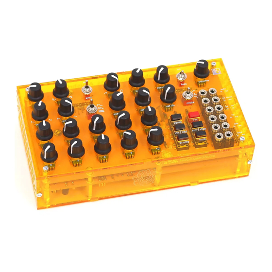
- Page 16 Mutable Instruments | Anushri - Assembly instructions 1/17/18, 8'04 AM Finally, add the MIDI connectors That’s it! You can insert the IC. Note that the TS912 used in the first batch of kits is now replaced by the more modern TLV2372. Here’s how the finished board looks like: https://mutable-instruments.net/archive/anushri/build/...
- Page 17 Mutable Instruments | Anushri - Assembly instructions 1/17/18, 8'04 AM Now, let’s move to the control board. Add the 6x 220R resistors (red, red, black, black). Add the 6x switches. Add the 6x LEDs. Note that they are polarized. The symbol printed on the board shows a round side (+) and a flat edge ().
- Page 18 Add the 4x 2x8 female connectors on the other side of the board. Anushri uses three different kinds of pots. Don’t mix them up! Add the 12x jack connectors. It is recommended to solder only one leg (the middle one) of all of them first, so that their position can be easily tweaked for optimal alignment.
-
Page 19: Test And Calibration
Mutable Instruments | Anushri - Assembly instructions 1/17/18, 8'04 AM on the PCB; and to identify the right part you can read “FA 100K” under the pot. If you are unsure which pot is which, check the resistance between the first and third lead before soldering them. -
Page 20: Mechanical Assembly
Mutable Instruments | Anushri - Assembly instructions 1/17/18, 8'04 AM through R25 falling apart, and deviation from exponential response from the SS2164. VCF calibration 1. Dial a patch in which the oscillators are silent. This can be achieved by enabling sync and setting the oscillators pitch to a very low value. -
Page 21: Troubleshooting
Mutable Instruments | Anushri - Assembly instructions 1/17/18, 8'04 AM … Then screw the top and bottom case panels to them, and finish the assembly of the case with the left, right, front and back panels. TROUBLESHOOTING Power distribution You can click on the image to open larger versions. -
Page 22: Signal Path
Mutable Instruments | Anushri - Assembly instructions 1/17/18, 8'04 AM cyan point: -4.1V, ±1%. Signal path Use one of the GND pads as a reference for voltage measurements. If you don’t have a scope, the verification of audio signals can be done by connecting the signal to a high-impedance amplifier (mixer or sound-card input, if possible switched to “high-Z”... - Page 23 Mutable Instruments | Anushri - Assembly instructions 1/17/18, 8'04 AM V: VCO tuning feedback signal. Square, should not go below ground. An oscilloscope is required for these checks. 10: Pot scanner signal. This is a sequence of 14 steps, each about 1.6ms wide, their amplitude equal to the position of each potentiometer.
Need help?
Do you have a question about the Anushri and is the answer not in the manual?
Questions and answers