Advertisement
Quick Links
Please refer to the online manual for detailed infor-
mation regarding compliance with EMC directives
www.mutable-instruments.net
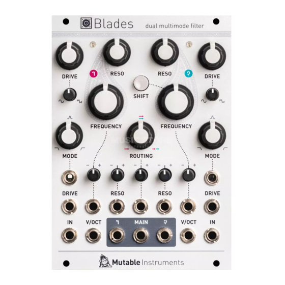
Controlling the signal path
IN 1
VCF 1
OUT 1
MAIN
no jack
inserted
jack
inserted
IN 2
VCF 2
OUT 2
The ROUTING knob
[G]
acts as a dual crossfader.
Firstly, it controls which proportion of fi lter 1 and fi lter
2's output is sent to the MAIN output (6): only fi lter 1
when turned fully CCW, only fi lter 2 when turned fully
CW, and both fi lters at 12 o'clock.
Secondly, it also controls which proportion of fi lter
1's input and fi lter 1's output is sent to fi lter 2's input
(provided fi lter 2's IN is left unpatched). As a result, the
following fi lter confi gurations can be obtained:
Single: the MAIN output carries the output of fi lter 1.
Parallel: the MAIN output carries a mix of fi lter 1 and
fi lter 2's outputs, and both fi lters process the same
signal from fi lter 1's input.
Series: the MAIN output carries the output of fi lter 2,
which processes fi lter 1's output.
If you patch your own signal source into fi lter 2's input,
then the ROUTING control simply acts as a crossfader
between fi lter 1 and 2's outputs.
Tips and patch ideas
•
Patch fi lter 2's output into fi lter 1's FREQUENCY CV
input and vice-versa for some chaotic effects.
•
Use fi lter 1 in self-oscillation as an oscillator
(possibly with feedback from its own output to its
FREQUENCY input to bend its waveform). Use fi lter
2 to wavefold and fi lter this raw waveform.
•
When a fi lter self-oscillates, and thus behaves as a
sine oscillator, its phase can be modulated through
the MODE CV input. This allows the synthesis of
metallic tones reminiscent of FM. Try modulating
MODE through a VCA, for CV-controlled adjustment
of phase-modulation depth.
•
With the two fi lters in series, both set to a low-pass
response, the module can be used as a voltage-con-
trolled distortion with pre- and post- tone controls.
•
Set fi lter 1 to a mild DRIVE, low FREQUENCY and
RESO, and choose the high-pass response. The
ROUTING knob now acts as a dry/wet control, for
whatever function fi lter 2 performs.
•
The intermediate responses between LP and BP,
or BP and HP, have a shelving shape. This can turn
Blades into a useful tool for EQ-ing and spectrally
coloring signals.
•
Since Blades' signal path is DC-coupled you can
also use it to process CV signals: use FREQUENCY
for portamento, RESO to add overshoot and wiggles.
DRIVE lets you control the signal amplitude or even
its shape.
Blades
Dual multimode fi lter
Advertisement

Related Manuals for Mutable Instruments Blades


Summary of Contents for Mutable Instruments Blades
- Page 1 Parallel: the MAIN output carries a mix of fi lter 1 and or BP and HP, have a shelving shape. This can turn fi lter 2’s outputs, and both fi lters process the same Blades into a useful tool for EQ-ing and spectrally signal from fi lter 1’s input. coloring signals.
- Page 2 2’s cutoff frequency will follow filter 1’s, Response of the drive circuit, continuously variable but transposed up (or down). Blades requires a -12V / +12V power supply (2x5 pin between round soft-clipping, and a two-stage wavefolder. connector). The red stripe of the ribbon cable (-12V side) Inputs and Outputs Filter input level indicator LED.
Need help?
Do you have a question about the Blades and is the answer not in the manual?
Questions and answers