Table of Contents
Advertisement
Quick Links
Advertisement
Chapters
Table of Contents

Subscribe to Our Youtube Channel
Related Manuals for R&S LCX Series


Summary of Contents for R&S LCX Series
- Page 1 ® R&S LCX Series LCR Meter User Manual (;ÝFÊ2) 1179226002 Version 02...
- Page 2 ® This manual describes the instruments of the R&S LCX Series, including options and measurement accessories: ● R&S ® LCX100 LCR Meter(3629.8856.02) ● ® R&S LCX200 LCR Meter (3629.8856.03) ● ® R&S NG-B105 Option IEE 488 (GPIB) interface (5601.6000.02) ●...
-
Page 3: Table Of Contents
® Contents R&S LCX Series Contents 1 Safety and regulatory information............9 Safety instructions......................9 Labels on the R&S LCX....................11 Warning messages in the documentation..............12 Korea certification class A..................12 2 Welcome....................13 Key features.........................13 3 Documentation overview..............14 Getting started manual....................14 User manual.........................14... - Page 4 ® Contents R&S LCX Series Instrument tour......................25 4.2.1 Front panel tour......................26 4.2.2 Rear panel tour......................29 Trying out the instrument...................32 Instrument control...................... 35 4.4.1 Ways to operate the instrument..................35 4.4.2 Means of manual interaction..................35 4.4.3 Remote control......................46 5 Measurement basics................47 Impedance measurement parameters in general.............47...
- Page 5 ® Contents R&S LCX Series 8.2.2 Configuring the main view.....................70 Measurement functions....................70 Test signal functions....................71 8.4.1 Test signal settings......................71 Measurement control functions.................72 Measurement parameters...................73 8.6.1 Measurement parameter settings................. 75 8.6.2 Open/short/load correction settings................78 8.6.3 Setting measurement parameters.................80 Configuration preset....................82 8.7.1...
- Page 6 ® Contents R&S LCX Series 9.5.1 Settings for CSV data....................122 9.5.2 Configuring CSV data....................123 Date & time........................ 123 Appearance........................124 Sound......................... 125 Licenses........................126 9.9.1 Licenses settings......................126 9.9.2 Managing licenses...................... 127 9.10 Device information....................129 9.10.1 Device information settings..................129 9.10.2 Using the dump file function..................130 9.11...
- Page 7 ® Contents R&S LCX Series 10.5 Adjusting interface addresses.................159 10.6 Operating the R&S LCX remotely................163 10.6.1 Controlling the R&S LCX over LAN................164 10.6.2 Accessing the file system of the R&S LCX using FTP..........167 11 Remote control commands...............171 11.1 Conventions used in SCPI command description..........
- Page 8 ® Contents R&S LCX Series 14.4 Disposal........................225 Glossary: List of the often used terms and abbreviations.....227 List of commands................230 Index....................233 User Manual 1179.2260.02 ─ 02...
-
Page 9: Safety And Regulatory Information
® Safety and regulatory information R&S LCX Series Safety instructions 1 Safety and regulatory information The product documentation helps you use the product safely and efficiently. Follow the instructions provided here and in the following chapters. Intended use The product is intended for the development, production and verification of electronic components and devices in industrial, administrative, and laboratory environments. - Page 10 ® Safety and regulatory information R&S LCX Series Safety instructions Choosing the operating site Only use the product indoors. The product casing is not waterproof. Water that enters can electrically connect the casing with live parts, which can lead to electric shock, serious personal injury or death if you touch the casing.
-
Page 11: Labels On The R&S Lcx
® Safety and regulatory information R&S LCX Series Labels on the R&S LCX ● If the product needs an external power supply, use the power supply that is deliv- ered with the product or that is recommended in the product documentation or a power supply that conforms to the country-specific regulations. -
Page 12: Warning Messages In The Documentation
® Safety and regulatory information R&S LCX Series Korea certification class A Chassis grounding connection Noiseless ground. The input signal at these connectors must be free from external voltages. The measurement results are otherwise incorrect. 1.3 Warning messages in the documentation A warning message points out a risk or danger that you need to be aware of. -
Page 13: Welcome
® Welcome R&S LCX Series Key features 2 Welcome 2.1 Key features The R&S LCX LCR Meter sets standards in analyzing passive components. It provides the full range of measurements to characterize resistors, capacitors and inductors, and displays results as absolute, relative or average values. -
Page 14: Documentation Overview
® Documentation overview R&S LCX Series Instrument security procedures 3 Documentation overview This section provides an overview of the R&S LCX user documentation. Unless speci- fied otherwise, you find the documents on the R&S LCX product page at: www.rohde-schwarz.com/manual/lcx 3.1 Getting started manual Introduces the R&S LCX and describes how to set up and start working with the prod-... -
Page 15: Printed Safety Instructions
® Documentation overview R&S LCX Series Remote control driver 3.6 Printed safety instructions Provides safety information in many languages. The printed document is delivered with the product. 3.7 Data sheets and brochures The data sheet contains the technical specifications of the R&S LCX. It also lists the firmware applications and their order numbers, and optional accessories. -
Page 16: Getting Started
® Getting started R&S LCX Series Preparing for use 4 Getting started This chapter contains the same information as the getting started manual. 4.1 Preparing for use Here, you can find basic information about setting up the product for the first time. -
Page 17: Setting Up The R&S Lcx
® Getting started R&S LCX Series Preparing for use ● Class A equipment is intended for use in industrial environments. It can cause radio disturbances in residential environments due to possible conducted and radi- ated disturbances. It is therefore not suitable for class B environments. -
Page 18: Considerations For Test Setup
® Getting started R&S LCX Series Preparing for use ● Keep a minimum distance of 10 cm between the fan openings of the product and any object in the vicinity. ● Do not place the product next to heat-generating equipment such as radiators or other products. -
Page 19: Connecting To Power
® Getting started R&S LCX Series Preparing for use To suppress electromagnetic radiation during operation: ● Use high-quality shielded cables, especially for the following connector types: – Connectors for external devices Double-shielded data cables. The length of data cables must not exceed 3 m. - Page 20 ® Getting started R&S LCX Series Preparing for use Do not use either fuse type other than specified, nor a defective fuse, and never short-circuit the fuse. Make sure that you have disconnected the R&S LCX from the mains. 2. Check the condition of the external bias fuse.
-
Page 21: Connecting To Lan
® Getting started R&S LCX Series Preparing for use e) Replace the fuse by a fuse of the specified type. A label next to the fuse holder also indicates the fuse type and its characteris- tics. Note: The protruding contact springs must not be deformed. Align the fuse holder with the guide bar facing the socket. -
Page 22: Connecting Usb Devices
® Getting started R&S LCX Series Preparing for use To connect the R&S LCX to the LAN: 1. Connect the "LAN" socket using an RJ-45 cable to the LAN. By default, the R&S LCX configuration uses DHCP that assigns the IP address automatically. -
Page 23: Connecting A Test Fixture
® Getting started R&S LCX Series Preparing for use To connect USB storage devices USB storage devices, such as memory sticks, allow easy data transfer from or to the R&S LCX. You can also use them for firmware updates. ► Connect the USB storage device to the "USB A" connector. - Page 24 ® Getting started R&S LCX Series Preparing for use Figure 4-2: Connecting a test fixture 2. Carefully plug the test fixture to the four "BNC" measurement connectors of the R&S LCX (2). 3. Turn all levers to the right to tighten the connection (3).
-
Page 25: Switching On Or Off
® Getting started R&S LCX Series Instrument tour 4.1.10 Switching on or off Switching on the product The product is off but connected to power. 1. Set the switch on the power supply to position [I]. The power supply switch connector is on the rear panel. -
Page 26: Front Panel Tour
® Getting started R&S LCX Series Instrument tour 4.2.1 Front panel tour Figure 4-4: R&S LCX front panel 1 = Basic display keys, see "Basic display keys" on page 27 2 = Touchscreen display, see Chapter 4.2.1.1, "Touchscreen display", on page 26 3 = Navigation controls, see "Navigation controls"... - Page 27 ® Getting started R&S LCX Series Instrument tour Figure 4-5: Touchscreen display For details on the screen display, see Chapter 4.4.2.1, "Understanding the display information", on page 36. The touch-sensitive panel provides an alternative means of user interaction for quick and easy handling of the instrument, see Chapter 4.4.2, "Means of manual...
- Page 28 ® Getting started R&S LCX Series Instrument tour Table 4-2: Navigation controls Assigned functions [Rotary knob] Selects, activates or confirms settings. [◀] / [▶] Moves the cursor in entry fields. [Back] Returns to a previous level in menus, or closes a view.
-
Page 29: Rear Panel Tour
® Getting started R&S LCX Series Instrument tour Table 4-6: Navigation controls Assigned functions [Auto] Activates the automatic selection of the measurement function. [Hold] Freezes the measurement range, on the screen indicated with prefix "Hold:" at the range value. [Trig.] Triggers a measurement manually. - Page 30 ® Getting started R&S LCX Series Instrument tour Figure 4-6: R&S LCX rear panel 1 = IEEE-488 interface, see "IEC 625/IEEE 488" on page 30 2 = Kensington lock, see "Kensington lock" on page 30 3 = AC power connector and power switch, see "AC power supply"...
- Page 31 ® Getting started R&S LCX Series Instrument tour Power supply connector for connecting the R&S LCX to the mains., see Chap- ter 4.1.6, "Connecting to power", on page 19. Ground terminal Protective ground terminal to secure the R&S LCX, e.g. with a grounded external con-...
-
Page 32: Trying Out The Instrument
® Getting started R&S LCX Series Trying out the instrument 4.3 Trying out the instrument As a brief introduction, the following example describes the basic steps to be taken when setting up a measurement. The instructions guide you through the measurement of a resistor. - Page 33 ® Getting started R&S LCX Series Trying out the instrument a) Press the [settings] key at the front panel. On the front panel, press the [settings] button. b) In the "Device" tab, select "Save/Recall Device Settings". c) Select "Default Settings".
- Page 34 ® Getting started R&S LCX Series Trying out the instrument 5. On the front panel, press the [Auto] key to activate automatic detection of the mea- surement function according to the component type of the DUT. Aligning the instrument on all frequencies To align the R&S LCX on all frequencies:...
-
Page 35: Instrument Control
® Getting started R&S LCX Series Instrument control 4.4 Instrument control This chapter provides an overview on how to work with the R&S LCX. It introduces the possibilities for operating the instrument and describes the basic functionality of the control elements. If a measurement configuration requires specific operating steps, the corresponding settings description in the user manual points it out separately. - Page 36 ® Getting started R&S LCX Series Instrument control Touch and swipe: Scrolls through the contents of a display element larger than the screen, e.g. a menu list. – Dragging Touch and drag: Shifts the contents from one position to another on the display.
- Page 37 ® Getting started R&S LCX Series Instrument control Figure 4-7: Example of screen display 1 = Configuration preset indicator, see "Configuration preset indicator" on page 37 2 = Status bars, see "Status bar" on page 37 3 = Settings softkey and configuration preset softkeys, see "Settings softkey"...
- Page 38 ® Getting started R&S LCX Series Instrument control ● gray - disabled ● red - faulty ● yellow - denotes a specific status Table 4-7: Instrument status bar Indicator Description Indicates that the touchscreen is locked. Chapter 9.3, "User button",...
- Page 39 ® Getting started R&S LCX Series Instrument control Indicator Description GPIB/IEE-488 The IEE-488 bus interface (GPIB) connection is established. Chapter 10.4, "Connecting the R&S LCX for remote access", on page 158. Time Indicates the time set on the instrument. Chapter 9.6, "Date &...
- Page 40 ® Getting started R&S LCX Series Instrument control Settings softkey (settings) softkey opens the measurement dialog for setting additional basic measurement parameters. Configuration preset softkeys (preset configuration) softkeys recall previously assigned measurement con- figurations, defined for dedicated measurements. You can assign up to three predefina- ble configuration presets.
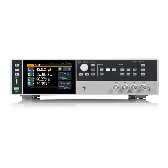
- Page 41 ® Getting started R&S LCX Series Instrument control Measurement parameters and results Figure 4-10: Measurement results window The initial screen shows the basic parameters capacitance "C " and serial resistance "R ", the impendance "Z" and phase angle "Θ ". On the right, the R&S LCX displays the measurement readings.
- Page 42 ® Getting started R&S LCX Series Instrument control Figure 4-11: Example of a menu ● Selection editors Figure 4-12: Example of selection editor for measurement parameter pairs When opened, a generic label in the header of the editor window shows the param- eter for selection.
- Page 43 ® Getting started R&S LCX Series Instrument control Figure 4-14: Alphanumeric on-screen keyboard ● Info dialogs An "Info dialog" appears when an event generates a message. The generically assigned header shows the affected topic. The message describes the event, and short instructions lead you through the next steps.
- Page 44 ® Getting started R&S LCX Series Instrument control To open a dialog To open one of the dialogs, or editors, you have several options: 1. Press the corresponding hardkey at the front panel, e.g. the [Freq.] key. 2. Select (tap) a softkey on the screen, e.g. "Frequency:"...
- Page 45 ® Getting started R&S LCX Series Instrument control To complete the entry To confirm the entry: ► On the on-screen keyboard, select (confirm). To abort the entry ► On the on-screen keypad, select "ESC". The dialog closes without changing the settings.
-
Page 46: Remote Control
® Getting started R&S LCX Series Instrument control b) Press the [rotary knob]. The selection editor opens. c) Turn the knob to scroll within the list. d) Press the [rotary knob] again to confirm your selection. 6. To access the main menus and subdialogs, use the functionality of the [rotary knob] and the [◀] or [▶] keys the same way. -
Page 47: Measurement Basics
® Measurement basics R&S LCX Series Impedance measurement parameters in general 5 Measurement basics The following graph shows the capacitive and inductive parts of passive components during impedance measurement in dependency on the frequency and the phase shift. Imaginary axis Q = 500 D = 0.002 Ω... -
Page 48: Impedance Measurement Parameters Of The R&S Lcx
® Measurement basics R&S LCX Series Impedance measurement parameters of the R&S LCX R (Ω) Resistance (Ω) Reactance Y (S) Admittance |Y| (S) Magnitude of Y Equivalent parallel conductance measured with par- allel-equivalent circuit model Susceptance Imaginary part of Y Quality factor (inverse of D) D or tanδ... - Page 49 ® Measurement basics R&S LCX Series Impedance measurement parameters of the R&S LCX Table 5-2: Resistance measurement parameters Parameter Designation and unit Rs-X series resistance (Ω) - reactance (Ω) Rp-B parallel resistance (Ω) - susceptance (Ω) DC current resistance (Ω) - reactance (Ω) conductance (S) - susceptance (Ω)
-
Page 50: Considerations On Measurement Accuracy
® Measurement basics R&S LCX Series Considerations on measurement accuracy Parameter Designation and unit Lp-Rp parallel inductance (H) - resistance (Ω) Lp-G parallel inductance (H) - conductance series resistance (Ω) - reactance (Ω) Rs-X conductance (S) - susceptance (Ω) impedance (Ω) - phase angle (rad) Z-Θr... - Page 51 ® Measurement basics R&S LCX Series Considerations on measurement accuracy How to: ● see the application note "LCX accuracy calculations" on the product page www.rohde-schwarz.com/application/lcx. The application note guides you how to proceed in general, and how to determine the value for specific sample components.
-
Page 52: Measurement Setups
® Measurement setups R&S LCX Series About test fixtures 6 Measurement setups Measuring components requires the use of suitable measurement adapters, referred to as test fixtures. 6.1 About test fixtures Test fixtures provide precise measurements of electronic components, such as passive components, either with lead wires or SMD modules. -
Page 53: Kelvin Clip Lead
® Measurement setups R&S LCX Series About test fixtures The R&S LCX-Z1 test adapter has two contact slots, each to plug in one lead of the component. To perform short correction, connect the short circuit plate supplied with the test fixture. For open correction, leave the slots unconnected. -
Page 54: Test Fixture For Smd Components
® Measurement setups R&S LCX Series About test fixtures 6.1.3 Test fixture for SMD components The R&S LCX-Z3 test fixture is designed for measuring SMD, i.e. leadless compo- nents. It is suitable for rectangular or cylindrical shaped chips with parallel electrodes, and components similar in shape and type. -
Page 55: Test Fixture With Cables For Transformer Components
® Measurement setups R&S LCX Series About test fixtures Figure 6-4: R&S LCX-Z4 SMD test tweezers The test fixture is equipped with tweezers, and miniature SMD tweezers. To perform short correction, close the hold contacts of the tweezers. For open correc- tion, leave the contacts open. - Page 56 ® Measurement setups R&S LCX Series About test fixtures Figure 6-5: R&S LCX-Z5 transformer test fixture and test cables The test fixture comes with four test leads equipped with alligator clips, to contact the primary and secondary circuits of the measurement sample. The BNC connectors on the right and left outside are intended to contact the circuit with the higher number of windings.
-
Page 57: Bnc-To-Bnc Extension
® Measurement setups R&S LCX Series Configuring the test signal 6.1.6 BNC-to-BNC extension The R&S LCX-Z11 BNC-to-BNC extension (1m) enables you to place the test setup in the distance of 1 m from the site of the R&S LCX. Figure 6-6: R&S LCX-Z11 BNC-to-BNC extension The extension also provides four BNC measurement ports for connecting a test fixture or establish user-specific connection. - Page 58 ® Measurement setups R&S LCX Series Configuring the test signal For details on the setting parameters, see Chapter 8, "Instrument functions", on page 67. The following sections provide additional information to be considered for the specific measurements. Depending on a bias required for your measurement, see Chapter 6.3, "Configuring...
-
Page 59: Configuring Bias
® Measurement setups R&S LCX Series Configuring BIAS For an example on how to configure the test signal parameters, see "Setting up the test signal" on page 33. 6.3 Configuring BIAS Referred to as biasing defines the method of superimposing a voltage or current on an existing voltage/current to shift the operating point of an electronic component to a spe- cific value. -
Page 60: External Voltage Bias
® Measurement setups R&S LCX Series Configuring BIAS a) Press the [Bias Level] key. b) Enter, e.g. 5 V using the keypad on the screen. 5. Confirm with 6. Set up the measurement of the capacitance as described, e.g. in "Measuring a... -
Page 61: Current Bias
® Measurement setups R&S LCX Series Configuring BIAS c) Confirm you selection. d) Repeat the steps to select the second parameters, e.g. select "Cp-D" (parallel capacitance, dissipation factor). 6. To set the voltage bias value: a) Press the [Bias Level] key. - Page 62 ® Measurement setups R&S LCX Series Configuring BIAS a) Select the measurement pair softkey in the upper left corner, to open the selec- tion editor. b) Select the parameters "Lp-Rp" (parallel inductance, parallel resistance). c) Confirm your selection. d) Repeat the steps to select the second parameters, e.g. select "Lp-Q" (parallel inductance, quality factor).
-
Page 63: Performing Measurements
® Performing measurements R&S LCX Series 7 Performing measurements Using the R&S LCX and the corresponding test fixture, you can measure various com- ponent types. The following description explains how to proceed for measuring the typ- ical components and what to consider. - Page 64 ® Performing measurements R&S LCX Series Decreasing the frequency reduces the loss angle, and thus the real components come closer to the ideal value. Measuring an inductor This example refers to a measurement of an inductor of 280 µH on a printed circuit board, by using the miniature SMD tweezers (R&S LCX-Z4).
- Page 65 ® Performing measurements R&S LCX Series H CUR primary secondary H POT open L POT L CUR Figure 7-1: Primary inductance measurement a) Connect the test leads of the corresponding circuit to one circuit of the sample transformer. b) Leave the second circuit of the transformer open.
- Page 66 ® Performing measurements R&S LCX Series To determine the mutual inductance, the R&S LCX calculates the parameters based on: = voltage in secondary circuit = resistance of secondary circuit = current in secondary circuit = current in primary circuit = inductance of secondary circuit...
-
Page 67: Instrument Functions
® Instrument functions R&S LCX Series Measurement mode 8 Instrument functions 8.1 Measurement mode The R&S LCX LCR meter two measurement modes: ● Continuous The instrument restarts the measurement automatically after a measurement cycle has been completed. Using this mode enables you to collect a series of measured values, e.g. to deter- mine value deviations of the component sample, or to determine tolerance ranges. -
Page 68: Working With The Measurement Modes
® Instrument functions R&S LCX Series Measurement mode Remote command: on page 207 MEASure:MODE Trigger source Selects the signal source that initiates the measurement in manual mode. Continuous Starts the measurement and continues after a completed measure- ment cycle automatically. -
Page 69: Display Mode
® Instrument functions R&S LCX Series Display mode 2. Press the [Trig.] key at the front panel, to start the measurement (Remote com- mand: on page 175). *TRG The R&S LCX executes one measurement cycle. When completed, it is waiting for the next trigger signal. -
Page 70: Configuring The Main View
® Instrument functions R&S LCX Series Measurement functions How to: see Chapter 8.2.2, "Configuring the main view", on page 70. <measurement pair>..................... 70 <measurement accuracy>.....................70 <measurement pair> Selects the measurement parameters. Depending on the type of component sample, the R&S LCX adjusts the list of parame- ters automatically. -
Page 71: Test Signal Functions
® Instrument functions R&S LCX Series Test signal functions 8.4 Test signal functions In this context referred to as test signal parameters, these parameters consider all set- tings the test signal is composed of. As the core parameters of a measurement, the R&S LCX provides the access to these settings directly on the screen, and the settings... -
Page 72: Measurement Control Functions
® Instrument functions R&S LCX Series Measurement control functions "Voltage Level" Sets the signal voltage. "Current Level" Sets the signal current. Remote command: on page 177 VOLTage[:LEVel] on page 177 CURRent[:LEVel] Range: / [Range] Selects the measurement range. Remote command:... -
Page 73: Measurement Parameters
® Instrument functions R&S LCX Series Measurement parameters [Auto]..........................73 [Hold]..........................73 [Trig.]..........................73 [Auto] Selects the impedance range automatically, according to the connected sample com- ponent. Note: If you have fixed the impedance range with [Hold] > ON, automatic selection is blocked. - Page 74 ® Instrument functions R&S LCX Series Measurement parameters measurement result. The cable length correction compensates these parasitic transmission characteristics. As a rule, make sure to keep the connection between the R&S LCX and the com- ponent under test as short as possible, even more, the length must not exceed 1 m.
-
Page 75: Measurement Parameter Settings
® Instrument functions R&S LCX Series Measurement parameters 8.6.1 Measurement parameter settings The "Measurement" parameters define additional settings that relate, e.g., to the mea- surement conditions. Access: 1. Press the [settings] key at the front panel. 2. Select the "Measurement" tab. - Page 76 ® Instrument functions R&S LCX Series Measurement parameters Auto Function........................ 77 └ Purity Angle.....................77 └ Serial/Paralell Separation Point..............77 Measurement Speed Selects the speed of the measurement repetitions per second. Using this speed parameter requires that you have set continuous triggering, see Chapter 8.1.1, "Measurement mode...
- Page 77 ® Instrument functions R&S LCX Series Measurement parameters "Low Z 10 Ω" Measures with 10 Ω output impedance. "High Z 100 Ω" Measures with 100 Ω output impedance. (default) Remote command: on page 197 FUNCtion:IMPedance:SOURce Trigger Delay Sets the delay between the trigger event and the actual start of the measurement.
-
Page 78: Open/Short/Load Correction Settings
® Instrument functions R&S LCX Series Measurement parameters Impedance Equivalent circuit 0 ≤ Z ≤ S serial measurement S < Z < range parallel measurement 8.6.2 Open/short/load correction settings The correction dialog enables you to activate and execute the correction techniques provided by the instrument. - Page 79 ® Instrument functions R&S LCX Series Measurement parameters Start Load Correction (Spot)..................80 Reference Load R......................80 Reference Load X......................80 Open/Short/Load Correction Enabled Enables the corresponding correction function. To start a correction process, select the corresponding Start Short/Open Correction...
-
Page 80: Setting Measurement Parameters
® Instrument functions R&S LCX Series Measurement parameters Remote command: on page 184 CORRection:OPEN[:EXECute] on page 184 CORRection:SHORt[:EXECute] Start Load Correction (Spot) Figure 8-6: Start load correction at one working point with specified reference value Executes the load correction at a defined working point. - Page 81 ® Instrument functions R&S LCX Series Measurement parameters Aligning the instrument on all frequencies To perform a full correction: 1. Set up the test signal, see "Setting up the test signal" on page 33. 2. If you are using the BNC-to-BNC extension (option R&S LCX-Z11), consider the cable length: a) Press the [settings] key at the front panel.
-
Page 82: Configuration Preset
® Instrument functions R&S LCX Series Configuration preset a) Select "Short Correction". b) Turn "Enabled". c) Select "Start Short Correction (Spot)". The R&S LCX displays a message that prompts you to short-circuit the termi- nals. d) Short-circuit the contacts, i.e. insert the supplied short circuit plate into the slots of the test fixture. -
Page 83: Configuration Preset Settings
® Instrument functions R&S LCX Series Configuration preset The configuration preset comprises almost all parameters relevant for a measure- ment: – Test signal: frequency and level – Measurement function: L/C/R/Transformer – Measurement speed – Cable length – DC voltage and low current states –... -
Page 84: Using The Configuration Preset Function
® Instrument functions R&S LCX Series Configuration preset Figure 8-7: Configuration preset indication 1 = Configuration preset indicator 2 = Settings softkey and configuration preset softkeys The configuration preset softkeys enable you to assign up to three different mea- surement configurations for quick access. -
Page 85: Specific Instrument Functions
® Instrument functions R&S LCX Series Specific instrument functions Creating user defined configuration presets To create and save a configuration preset: 1. Select the configuration preset memory slot, e.g. 2. Select to open the parameter settings dialog. 3. Set the corresponding parameters. -
Page 86: Live Chart Viewer
® Instrument functions R&S LCX Series Specific instrument functions Figure 8-8: Functions menu 3. Select the corresponding function in the list. ● Live chart viewer..................... 86 ● Logging chart viewer....................89 ● Logging........................94 ● Dynamic impedance measurement.................98 ● Binning........................102 8.8.1 Live chart viewer... - Page 87 ® Instrument functions R&S LCX Series Specific instrument functions The graphical results display shows the traces of the measurement results for the selected parameters. The softkeys enable you to select the parameters for display according to your measurement. How to: see Chapter 8.8.1.2, "Displaying the readings in the live...
- Page 88 ® Instrument functions R&S LCX Series Specific instrument functions Indicates the time scaling of the x-axis in the chart. <measurement parameter> Indicates the selected measurement parameter with the specified unit per division. Back Returns to the "Functions" tab. Clear Resets the chart and restarts graphical display of the measurement.
-
Page 89: Logging Chart Viewer
® Instrument functions R&S LCX Series Specific instrument functions b) In the "Data Source" list, select the parameter, e.g. "Impedance (Z)". c) Select a color for the parameter trace. d) To show the minimum and maximum readings of the selected parameter, turn "Show Min/Max". - Page 90 ® Instrument functions R&S LCX Series Specific instrument functions 2. In the "Functions" tab, select "Open Log Chart". Figure 8-14: Log chart view The graphical results display shows the traces of the measurement results for the selected parameters. The softkeys enable you to select the parameters for display according to your measurement.
- Page 91 ® Instrument functions R&S LCX Series Specific instrument functions Figure 8-15: Log chart controls 1 = File name of the logging file 2 = Parameter pair softkeys 3 = Reset softkey 4 = Resolution softkey 5 = Capture indicator when touching and dragging within the graph...
- Page 92 ® Instrument functions R&S LCX Series Specific instrument functions Reset View Resets the graphical display to the initial resolution. - x1 + Sets the resolution of the graphical display. You can increase or decrease the resolution by the predefined multiplication factors "x1", "x2", "x5", "x10", "x25"...
- Page 93 ® Instrument functions R&S LCX Series Specific instrument functions 3. To configure a parameter for display: a) Select a parameter softkey on the right of the display. The "Configure Chart Trace <n>" dialog opens. Figure 8-17: Configure chart trace dialog b) In the "Data Source"...
-
Page 94: Logging
® Instrument functions R&S LCX Series Specific instrument functions The R&S LCX uploads the data and displays all information on the screen. Figure 8-19: Log chart result The labels of the parameter softkeys indicate the measured parameter with the respective unit per grid in the diagram. The colored bar of each softkey corre- sponds to the trace color. -
Page 95: Enabled
® Instrument functions R&S LCX Series Specific instrument functions 2. In the "Functions" tab, select "Logging". Figure 8-20: Network settings dialog The settings dialog contains the basic parameters for setting the logging mode, and provides access to file management parameters. -
Page 96: Target Folder
® Instrument functions R&S LCX Series Specific instrument functions "Auto" Selects the target folder automatically. "Manual" Enables you to select and define the target folder on the USB stick. Target Folder With a USB stick connected, accesses a dialog to select the memory partition where you want to save the file. -
Page 97: Count
® Instrument functions R&S LCX Series Specific instrument functions Remote command: on page 203 LOG:INTerval Count Sets the number of measurement readings for data logging Mode > Count. Remote command: on page 202 LOG:COUNt Duration Sets the time period for data logging Mode >... -
Page 98: Dynamic Impedance Measurement
® Instrument functions R&S LCX Series Specific instrument functions 4. If you have connected an external USB memory device: a) Select "Target Folder". The R&S LCX opens a selection editor. b) Select "USB1A". c) Confirm with "Select". Note: With no USB connected, the instrument displays a message and automati- cally sets the internal partition, when confirmed. - Page 99 ® Instrument functions R&S LCX Series Specific instrument functions When activated, the R&S LCX starts sweeping through the range of measurement sig- nal parameter values and records the acquired measurement data in a log file. When the sweep process is completed, the instrument displays the recorded measurement data graphically.
- Page 100 ® Instrument functions R&S LCX Series Specific instrument functions Enabled........................100 Sweep Parameter....................... 100 Minimum........................100 Maximum........................100 Interval Type........................100 Step Size........................101 Number of Points......................101 Abort..........................101 Enabled Starts the dynamic impedance measurement process. The R&S LCX displays a progress dialog until the measurement is complete, see "Measuring in dynamic impedance measurement mode"...
- Page 101 ® Instrument functions R&S LCX Series Specific instrument functions "Step Size" Uses the interval between one sweep parameter value to the next, set with Step Size. "Number of Points" Uses the number of values within the range of minimum and maxi-...
-
Page 102: Binning
® Instrument functions R&S LCX Series Specific instrument functions 4. Depending on the selected interval type, configure the value for the step size or the number of points to set the values of the sweep parameter within the range. 5. To start the dynamic impedance measurement process, turn "Enabled". - Page 103 ® Instrument functions R&S LCX Series Specific instrument functions The binning function enables you to sort a set of electrical components according to the measured characteristics. The R&S LCX measures a connected component and categorizes it based on a predefined bin configuration. You can see the corresponding result on the screen, and also get the category assigned at one of the digital outputs of the interface I/O port.
- Page 104 ® Instrument functions R&S LCX Series Specific instrument functions For details on the trigger modes, see the data sheet, section "Digital trigger and control interfaces". 8.8.5.2 Assignment of the binning interface The digital I/O port of the binning interface is a 15-pole D-Sub female socket, including eight data lines.
- Page 105 ® Instrument functions R&S LCX Series Specific instrument functions The required remote commands are described in Chapter 11.11, "HANDler subsys- tem", on page 198. Enabled........................105 Load From File......................105 Enabled Enables the sorting function. The measurement starts with a trigger signal.
- Page 106 ® Instrument functions R&S LCX Series Specific instrument functions 4. In the binning menu, activate binning. Figure 8-24: Binning measurement results window 1 = Measurement function indicator 2 = Settings softkey 3 = CSV file 4 = Counter 5 = Sorting characteristics...
- Page 107 ® Instrument functions R&S LCX Series Specific instrument functions Binning Indicates the measurement mode that you are working in. Settings softkey (settings) softkey returns to the binning menu, see Chapter 8.8.5.3, "Binning settings", on page 104. <filename> Indicates the binning *csv the measurement is based on.
- Page 108 ® Instrument functions R&S LCX Series Specific instrument functions Histogram Displays the percentage distribution over the bins. 8.8.5.5 Configuring and using the binning function Configuring a binning file To specify the file for the binning measurement, proceed as follows: 1. On a PC, open an application that can store data in *.csv format, e.g. a spread- sheet application.
- Page 109 ® Instrument functions R&S LCX Series Specific instrument functions Example: Binning configuration data for a resistor measurement The example defines a binning measurement that returns the measurement results for the resistance and impedance parameter pair (Rs-X), specified for 4 measurement cat- egories.
- Page 110 ® Instrument functions R&S LCX Series Specific instrument functions Executing a binning measurement A binning measurement requires that you configure the test signal and all settings nec- essary for your measurement before. You cannot change a parameter while the mea- surement is running.
-
Page 111: General Instrument Settings
® General instrument settings R&S LCX Series 9 General instrument settings The general instrument settings include basic instrument functions, regardless of the selected operating mode and measurement. Some of these settings like screen display and peripherals are initially configured at the setup of the instrument, according to per- sonal preferences and requirements. -
Page 112: File And Data Management
® General instrument settings R&S LCX Series File and data management ● Licenses........................126 ● Device information....................129 ● Update device....................... 131 ● Save/recall......................133 ● Customizing general instrument settings.............. 136 9.1 File and data management The R&S LCX uses files to save all instrument data, e.g., instrument configuration and settings, measurement data or created screenshots of the current settings displayed on the screen. -
Page 113: File Manager Settings
® General instrument settings R&S LCX Series File and data management File names The R&S LCX assigns generic file names to internally created files, composed of an identification of the function, if applicable, and a time stamp. For user-specific files, you can assign a dedicated file name. -
Page 114: Using The File Manager
® General instrument settings R&S LCX Series File and data management Figure 9-2: File manager dialog The "File Manager" dialog shows a navigator of the memory directories, and you can copy or delete files, as known from common file explorers. The functions provi- ded are self-explanatory in conjunction with the softkeys labeled accordingly. - Page 115 ® General instrument settings R&S LCX Series File and data management Figure 9-3: File information Retrieving device documentation You can retrieve the R&S LCX Open Source Acknowledgment documentation from the instrument documentation folder /int/documentation. To view information on the selected file: 1.
-
Page 116: Data And File Types
® General instrument settings R&S LCX Series Interfaces 9.1.3 Data and file types The R&S LCX distinguishes the files according to their extensions; each type of file is assigned a specific file content and also a specific file extension. The extension is pre- defined, e.g. -
Page 117: Interface Settings
® General instrument settings R&S LCX Series Interfaces 9.2.1 Interface settings Access: 1. Press the [settings] key at the front panel. 2. In the "Device" tab, select "Interfaces". 3. Select the corresponding menu item. Figure 9-5: Interfaces menu In the "Interfaces" menu, you can access the settings dialogs for configuring the general network environment and specific identification parameters of the instru- ment. -
Page 118: Configuring Interfaces
® General instrument settings R&S LCX Series User button 9.2.2 Configuring interfaces As the information on how to establish and configure a remote control connection relates closely to the remote control environment, see: ● Chapter 10.4, "Connecting the R&S LCX for remote access",... -
Page 119: Using The User Button Function
® General instrument settings R&S LCX Series Screenshot How to: see "Assigning the touch lock function to the "User Button"" on page 119 ● "Open Correction", starts calibration on all frequencies for open test fixtures contacts. How to: see Chapter 6.2, "Configuring the test signal",... -
Page 120: Screenshot Settings
® General instrument settings R&S LCX Series Screenshot How to: see Chapter 9.4.2, "Using the screenshot function", on page 120. 9.4.1 Screenshot settings With a USB stick connected, you can save the file on either the USB stick or the inter- nal memory, with "USB1A"... - Page 121 ® General instrument settings R&S LCX Series Screenshot Without a USB memory stick connected, the R&S LCX saves the file internally under / int/screenshot. Chapter 9.1, "File and data management", on page 112 for information on how to access the memory and manage file export.
-
Page 122: Csv Settings
® General instrument settings R&S LCX Series CSV settings For further use of the screenshots, you can open the files in any application that supports *.png file format. For information on how to access the memory and manage file export, see Chap- ter 9.1, "File and data... -
Page 123: Configuring Csv Data
® General instrument settings R&S LCX Series Date & time Field Delimiter Selects the line separator between individual parameters or values. "Semicolon" Separates the data entries by a semicolon. "Comma" Uses a comma. Decimal Separator Selects the decimal separator for values. -
Page 124: Appearance
® General instrument settings R&S LCX Series Appearance The time is regarded as UTC. There is no timezone selectable. The R&S LCX records the time during operation and creates a time stamp on printed outputs or in saved datasets. Access: 1. -
Page 125: Sound
® General instrument settings R&S LCX Series Sound Access: 1. Press the [settings] key at the front panel. 2. In the "Device" tab, select "Appearance". Figure 9-10: Appearance settings menu The appearance menu provides access to on-screen editors for adjusting the brightness of the screen and front panel keys. -
Page 126: Licenses
® General instrument settings R&S LCX Series Licenses Figure 9-11: Sound settings menu In the "Sound Settings" dialog, you can set an alert. The required remote commands are described in Chapter 11.15, "SYSTem subsys- tem", on page 211. How to: see "Customizing the sound settings"... -
Page 127: Managing Licenses
® General instrument settings R&S LCX Series Licenses Figure 9-12: Licenses dialog The licenses dialog provides all information on installed licenses and their current activity state: ● "Active" displays options that are currently activate in the instrument. ● "Inactive" displays options that are installed but currently not active. - Page 128 ® General instrument settings R&S LCX Series Licenses 4. Select "Load File" to load the license file from the USB stick. The R&S LCX applies the license key. It displays a message "Devicekey is instal- led". Note: For the license to take effect, the R&S LCX must reboot.
-
Page 129: Device Information
® General instrument settings R&S LCX Series Device information 2. To remove the option manually, select "Remove" in the license dialog. The R&S LCX displays the "Enter Deactivation Key" on-screen keypad. 3. To enter the license key, proceed the same way as described in "Inserting the... -
Page 130: Using The Dump File Function
® General instrument settings R&S LCX Series Device information "Model" Designation of the instrument. "ID" Part number of the instrument. "Serial No.:" Serial number of the instrument. "Version" Currently installed firmware version. How to: see Chapter 9.11, "Update device", on page 131 "FPGA"... -
Page 131: Update Device
® General instrument settings R&S LCX Series Update device 5. Now you can send the file to your local service department. 9.11 Update device The update functionality enables you to update the firmware of the instrument. Using the USB interface at the front panel, you can provide the installation file for the update. -
Page 132: Updating The Instrument Software
® General instrument settings R&S LCX Series Update device UPDATE Starts the software update. 9.11.2 Updating the instrument software The following instructions show how to proceed for updating the instrument software version on the instrument. Updating the instrument software We recommend that you use the latest software version available on the product page at www.rohde-schwarz.com/firmware/lcx. -
Page 133: Save/Recall
® General instrument settings R&S LCX Series Save/recall 9.12 Save/recall The "Save/Recall" function enables you to save a certain configuration in a file and reload it for later reuse. On power-on, the R&S LCX starts up in the configuration you used before switching off. -
Page 134: Using The Save/Recall Function
® General instrument settings R&S LCX Series Save/recall Recall Settings from file... Reloads a previously saved instrument configuration. Default Settings Sets all parameters except for system settings to default. Factory Reset Resets the instrument to the initial factory settings. 9.12.2 Using the save/recall function You can save the current instrument settings to a file, and load these settings in one step again, e.g. - Page 135 ® General instrument settings R&S LCX Series Save/recall The R&S LCX leads you to the memory location to select the file. 3. Confirm you selection with "Load". The R&S LCX applies the loaded settings. Recalling default instrument settings You can reset all instrument settings to factory default values, without affecting your specific system settings.
-
Page 136: Customizing General Instrument Settings
® General instrument settings R&S LCX Series Customizing general instrument settings 3. If confirmed, a second message provides to delete all internally saved files. 4. Confirm the prompt accordingly. The R&S LCX resets all instrument settings to factory default and shuts down. - Page 137 ® General instrument settings R&S LCX Series Customizing general instrument settings a) Select the "Set Time" softkey. An on-screen editor with clock entries opens. Figure 9-16: Time editor b) Select "Hour" and "Minute". c) Confirm your entry. 5. To change the clock format: a) Select "Change Clock Format"...
- Page 138 ® General instrument settings R&S LCX Series Customizing general instrument settings a) Select the corresponding softkey. Figure 9-18: Brightness editor b) Shift the scrollbar to the right, or to the left, e.g. to set "50%". c) Confirm with "OK". 4. Close the appearance dialog with "OK".
-
Page 139: Network Operation And Remote Control
® Network operation and remote control R&S LCX Series 10 Network operation and remote control As an alternative to the interactive operation directly at the instrument, you can operate the R&S LCX also from a remote control location, for example a controller PC. -
Page 140: Overview Of Remote Access Modes
® Network operation and remote control R&S LCX Series Overview of remote access modes 10.1 Overview of remote access modes This section outlines the possible access modes and their major characteristics. Remote control (SCPI) ● A remote PC controls the instrument, usually using VISA (Virtual Instrument Soft- ware Architecture) interfaces. -
Page 141: Remote Control Interfaces And Protocols
® Network operation and remote control R&S LCX Series Remote control interfaces and protocols Remote file access (FTP) ● A remote client device accesses the instrument's file system over an Ethernet con- nection, using FTP (file transfer protocol). ● The protocol enables you to get direct access to the file directory of the R&S LCX to transfer files from or to the instrument. -
Page 142: Lan Interface
® Network operation and remote control R&S LCX Series Remote control interfaces and protocols Interface Remarks Protocols, VISA address string and library ● – GPIB (IEC/IEEE Bus The optional GPIB bus interface according to GPIB::<address>[::INSTR] (no secondary Interface) standard IEC 625.1/IEEE 488.1 is at the... - Page 143 ® Network operation and remote control R&S LCX Series Remote control interfaces and protocols composed of the specific IP address of the instrument and some network and VISA- specific keywords. TCPIP::<host address>[::<LAN device name>][::INSTR] TCPIP = designates the network protocol...
-
Page 144: Usb Interface
® Network operation and remote control R&S LCX Series Remote control interfaces and protocols To assign a user-specific port number, see Chapter 10.5, "Adjusting interface addresses", on page 159. FTP communication ftp://<host address>[::<port>] port = determines the used port number By default, instruments from Rohde &... -
Page 145: Gpib Interface (Iec/Ieee Bus Interface)
® Network operation and remote control R&S LCX Series Remote control interfaces and protocols For control, you can use the SCPI terminal function of the R&S HMExplorer soft- ware. This software also provides logging of measurement values, or graphical dis- play. -
Page 146: Status Reporting System
® Network operation and remote control R&S LCX Series Remote control interfaces and protocols GPIB address The controller addresses the instrument with the GPIB bus channel, see Chapter 9.2.1, "Interface settings", on page 117. GPIB provides channel addresses from 0 to 30. The... - Page 147 ® Network operation and remote control R&S LCX Series Remote control interfaces and protocols 10.2.4.1 Overview of the R&S LCX status registers Questionable I-BIAS OV Output-Queue Channel 1 Status Ext. V-BIAS OV Channel 2 I-BIAS Analog FB Sat Channel 3...
- Page 148 ® Network operation and remote control R&S LCX Series Remote control interfaces and protocols To read the register, use the query commands STATus:OPERation:CONDition? on page 209 or on page 209. The remote com- STATus:OPERation[:EVENt]? mands for the operation status register are described in Chapter 11.14.1, "Status oper-...
-
Page 149: Remote Access Settings
® Network operation and remote control R&S LCX Series Remote access settings Table 10-4: Assignment of the bits used in the questionable status register Bit No. Meaning I-BIAS OV Ext. V-BIAS OV I-BIAS Analog FB Sat LCUR outamp DC OV... - Page 150 ® Network operation and remote control R&S LCX Series Remote access settings Figure 10-3: Network settings dialog In the "Network" dialog, you can access the LAN and VNC interface addresses, assign the port for raw socket communication and a hostname for the instrument.
-
Page 151: Lan Settings
® Network operation and remote control R&S LCX Series Remote access settings Remote command: "SCPI Raw Port" on page 150 Desired Hostname Displays the hostname. Each instrument is delivered with an assigned hostname, a logical name you can use instead of the IP address. - Page 152 ® Network operation and remote control R&S LCX Series Remote access settings Figure 10-4: LAN settings dialog In this dialog, you can configure the settings of the general network environment and specific identification parameters of the instrument in the network. The R&S LCX displays the VISA resource strings and additional parameters for infor-...
-
Page 153: Vnc Settings
® Network operation and remote control R&S LCX Series Remote access settings Remote command: on page 217 SYSTem:COMMunicate:LAN:ADDRess Subnet Mask Displays the bit group of the subnet in the host identifier. To assign the subnet mask manually, set DHCP & Auto-IP >... -
Page 154: Ftp Settings
® Network operation and remote control R&S LCX Series Remote access settings Access: 1. Press the [settings] key at the front panel. 2. In the device settings menu, select "Interfaces". 3. Select "Network". 4. Select "VNC". Figure 10-5: VNC settings dialog The "VNC"... - Page 155 ® Network operation and remote control R&S LCX Series Remote access settings Using an FTP client application on a computer, you can access the internal memory or a connected USB memory stick of the R&S LCX. The connection enables you to trans- fer files with operating data, saved device settings, measurement data files or docu- ments from or to the device.
-
Page 156: Usb Settings
® Network operation and remote control R&S LCX Series Remote access settings The R&S LCX uses port 21 by default, but you can use any port address in the range of 100 to 65635. How to: see "Assigning the FTP port address manually"... -
Page 157: Gpib Settings
® Network operation and remote control R&S LCX Series Remote access settings The R&S LCX supports CDC and TMC communication, see Chapter 10.2.2, "USB interface", on page 144. Note: If you change the "USB Class", you must reboot the instrument to load the corre- sponding USB driver, see "Selecting the USB communication class protocol"... -
Page 158: Connecting The R&S Lcx For Remote Access
® Network operation and remote control R&S LCX Series Connecting the R&S LCX for remote access 10.4 Connecting the R&S LCX for remote access This section briefly explains how to set up the remote control connections for the inter- faces provided by the R&S LCX. -
Page 159: Adjusting Interface Addresses
® Network operation and remote control R&S LCX Series Adjusting interface addresses The USB B connector is at the rear panel. To connect the R&S LCX to the controller PC: 1. Connect the IEC 625/IEEE 488 connector of the R&S LCX to the controller PC with a double-shielded GPIB bus interface cable. - Page 160 ® Network operation and remote control R&S LCX Series Adjusting interface addresses Figure 10-9: LAN settings The R&S LCX enables edit mode. 4. Select the "IP Address". The IP address consists of four blocks separated by dots. Every block contains 3 numbers at a maximum.
- Page 161 ® Network operation and remote control R&S LCX Series Adjusting interface addresses 3. Turn VNC. 4. Select "VNC Port". An on-screen keypad opens. 5. Enter the port number. 6. Confirm with The R&S LCX changes the VNC port address accordingly.
- Page 162 ® Network operation and remote control R&S LCX Series Adjusting interface addresses c) Confirm with The R&S LCX changes the FTP port address accordingly. Note: The FTP address settings are retained by an instrument preset, and also when you recall previously saved instrument settings, see Chapter 9.12, "Save/...
-
Page 163: Operating The R&S Lcx Remotely
® Network operation and remote control R&S LCX Series Operating the R&S LCX remotely The instrument must reboot to load the corresponding protocol driver. 5. To proceed, you have the following options: a) Confirm with "OK". The R&S LCX reboots and activates the connection. It indicates the selected USB interface port in the device status bar on top of the screen. -
Page 164: Controlling The R&S Lcx Over Lan
® Network operation and remote control R&S LCX Series Operating the R&S LCX remotely ● You have established the correct interface address, see Chapter 10.2, "Remote control interfaces and protocols", on page 141. 10.6.1 Controlling the R&S LCX over LAN 10.6.1.1... - Page 165 ® Network operation and remote control R&S LCX Series Operating the R&S LCX remotely 10.6.1.2 Accessing the R&S LCX over VNC Enabling the VNC service for remote access For remote access over VNC, you must connect the controller PC and the R&S LCX in a LAN, see "Establishing the LAN connection"...
- Page 166 ® Network operation and remote control R&S LCX Series Operating the R&S LCX remotely Tip: If you want to configure a different port, enter the port and confirm with "Con- nect". 5. To zoom the instrument view, select "Open in fullscreen".
-
Page 167: Accessing The File System Of The R&S Lcx Using Ftp
® Network operation and remote control R&S LCX Series Operating the R&S LCX remotely 4. Confirm with enter. An icon of the LCR meter appears on the VNC viewer window. 5. Select the icon to open the remote desktop of the instrument. - Page 168 ® Network operation and remote control R&S LCX Series Operating the R&S LCX remotely 9. Turn "DHCP & Auto IP". The R&S LCX indicates the IP address, you can use for accessing the instruments file system over FTP protocol, see Accessing the file system remotely over a file explorer.
- Page 169 ® Network operation and remote control R&S LCX Series Operating the R&S LCX remotely To mount the FTP network address string to the file explorer: 1. Open the file explorer on the controller PC. 2. Connect to the R&S LCX file system as described in...
- Page 170 ® Network operation and remote control R&S LCX Series Operating the R&S LCX remotely Wait until an ongoing transfer process has finished. 2. Close the FTP client application. 3. To reconnect, proceed as described above. User Manual 1179.2260.02 ─ 02...
-
Page 171: Remote Control Commands
® Remote control commands R&S LCX Series Conventions used in SCPI command description 11 Remote control commands In the following, all remote-control commands are presented in detail with their param- eters and the ranges of numerical values. For an introduction to remote control and the status registers, see: ●... -
Page 172: Programming Examples
® Remote control commands R&S LCX Series Common commands 11.2 Programming examples The corresponding sections of the same title provide simple programming examples for the R&S LCX. The purpose of the examples is to present all commands for a given task. - Page 173 ® Remote control commands R&S LCX Series Common commands ...........................174 *STB? ..........................175 *TRG ..........................175 *WAI *CLS Clear status Sets the status byte (STB), the standard event register (ESR) and the EVENt part of the QUEStionable and the OPERation registers to zero. The command does not alter the mask and transition parts of the registers.
- Page 174 ® Remote control commands R&S LCX Series Common commands Sets bit 0 in the event status register when all preceding commands have been execu- ted. This bit can be used to initiate a service request. The query writes a "1" into the output buffer when all preceding commands have been executed, which is useful for command synchronization.
-
Page 175: Test Signal Commands
® Remote control commands R&S LCX Series Test signal commands *TRG Trigger Triggers all actions waiting for a trigger event. In particular, *TRG generates a manual trigger signal. This common command complements the commands of the TRIGger subsystem. Usage: Event Manual operation: "Trigger source"... - Page 176 ® Remote control commands R&S LCX Series Test signal commands Example: Setting key parameters The example represents the main remote control commands for the test signal, and measurement environment. ************************************************** // Set frequency and voltage level of the test signal FREQuency[:CW] 1000 // 1 KHz VOLTage[:LEVel] 1 // 1.00 Vrms...
- Page 177 ® Remote control commands R&S LCX Series Test signal commands SHORt Sets the measurement time ≤.015 s. MEDium Sets the measurement time ≤0.100 s. LONG Sets the measurement time ≤0.500 s. DEFault Uses the default setting "SHORt". Example: Example "Setting key parameters"...
-
Page 178: Bias Subsystem
® Remote control commands R&S LCX Series BIAS subsystem MAX | MAXimum Queries the upper limit of the signal level. DEF | DEFault Queries the signal level the instrument sets by default. Range: 0.01 V to 10 V *RST: Default unit: V Example: Example "Setting key parameters"... - Page 179 ® Remote control commands R&S LCX Series BIAS subsystem BIAS:EXTernal:MEASure:VOLTage? Queries the value of the externally applied voltage. Parameters for setting and query: <voltage> Default unit: V Example: Example "Bias settings" on page 178. Usage: Query only BIAS:EXTernal[:VOLTage][:STATe] <External Voltage Bias State>...
-
Page 180: Correction Subsystem
® Remote control commands R&S LCX Series CORRection subsystem Manual operation: "Voltage Bias: / [Bias Level]" on page 72 11.6 CORRection subsystem The CORRection subsystem contains the commands for controlling the Open/Short and Load correction operations. User Manual 1179.2260.02 ─ 02... - Page 181 ® Remote control commands R&S LCX Series CORRection subsystem Example: Setting correction prameters The example represents the remote control commands to configure the correction set- tings. // Configure the corrections settings: // set the cable length between the DUT and the instument...
-
Page 182: Correction:spot
® Remote control commands R&S LCX Series CORRection subsystem // Response: 1 // running CORRection:SHORt:STATe? CORRection:LOAD:STATe? // *************************** // Activate the working point for correction // of a single component. CORRection:USE:DATA:SINGle 0.8 // Select the channel for activating a working point...:Open[:Execute] -
Page 183: Correction:load:state
® Remote control commands R&S LCX Series CORRection subsystem Parameters: <Cable Length> Range: 0 m to 1 m *RST: Default unit: m Example: Example "Setting correction prameters" on page 181. Manual operation: "Cable Length" on page 76 "Test Signal Type"... -
Page 184: Correction:open[:Execute]
® Remote control commands R&S LCX Series CORRection subsystem Parameters: <Open Correction 1 | 0 | ON | OFF State> *RST: 0|OFF Example: Example "Setting correction prameters" on page 181. Manual operation: "Open/Short/Load Correction Enabled" on page 79 CORRection:OPEN[:EXECute] Executes an open correction on all frequencies. -
Page 185: Correction:spot
® Remote control commands R&S LCX Series CORRection subsystem CORRection:SPOT<Spot>:LOAD:STANdard <Reference value for primary>, <Reference value for secondary> Defines a working point for load correction. Assign the working point number and the primary and secondary reference values. Suffix: <Spot> 1..n Parameters: <Reference value for...:Load:standard -
Page 186: Data Subsystem
® Remote control commands R&S LCX Series DATA subsystem Example: Example "Setting correction prameters" on page 181. CORRection:USE:DATA:SINGle <Use single data state> Activates the correction value for a test point when you measure a single component. Parameters: <Use single data 1 | 0 | ON | OFF state>... - Page 187 ® Remote control commands R&S LCX Series DATA subsystem Example: Managing files The example represents the remote control commands to manage files in directories. ************************************************** // Request information on files // and their contents: // list of files in a directory,number of measurement // points in a file, the saved readings.
-
Page 188: Dimeasure Subsystem
® Remote control commands R&S LCX Series DIMeasure subsystem Usage: Query only Manual operation: "Delete" on page 114 DATA:POINts? <File Path> Queries the number of measurement readings saved in a file. Query parameters: <File Path> Example: Chapter 11.7, "DATA subsystem", on page 186. - Page 189 ® Remote control commands R&S LCX Series DIMeasure subsystem Example: Using the DIMeasure function The example represents the remote control commands for setting up a dynamic impe- dance measurement. ************************************************* // Select the sweep parameter to be varied. // Configure the corresponding sweep parameters.
- Page 190 ® Remote control commands R&S LCX Series DIMeasure subsystem ************************************************* // Cancel a running dynamic impedance measurement DIMeasure:ABORt ......................190 DIMeasure:ABORt ...................... 190 DIMeasure:EXECute .................... 190 DIMeasure:INTerval:POINts ..................190 DIMeasure:INTerval:STEPsize ....................191 DIMeasure:INTerval:TYPE ..................191 DIMeasure:SWEep:MAXimum ..................191 DIMeasure:SWEep:MINimum ..................192 DIMeasure:SWEep:PARameter DIMeasure:ABORt Stops a running dynamic impedance measurement.
- Page 191 ® Remote control commands R&S LCX Series DIMeasure subsystem Parameters: <Interval stepsize> numeric Example: Example "Using the DIMeasure function" on page 189. Options: Option: R&S LCX-K106 Manual operation: "Step Size" on page 101 DIMeasure:INTerval:TYPE <Interval parameter> DIMeasure:INTerval:TYPE? <Interval parameter> Selects the mode to determine the measurement steps within the sweep range (DIMeasure:SWEep:MINimum to DIMeasure:SWEep:MAXimum).
-
Page 192: Display Subsystem
® Remote control commands R&S LCX Series DISPLay subsystem Parameters: <Sweep start value> numeric Example: Example "Using the DIMeasure function" on page 189. Options: Option: R&S LCX-K106 Manual operation: "Minimum" on page 100 DIMeasure:SWEep:PARameter <Sweep parameter> DIMeasure:SWEep:PARameter? <Sweep parameter> Selects the measurement parameter that varies in defined steps within the sweep range (DIMeasure:SWEep:MINimum. - Page 193 ® Remote control commands R&S LCX Series DISPLay subsystem Example: Configuring the display brightness and user defined text messages The example represents the remote control commands for setting the brightness of the screen and front panel keys. For description of the key brightness command, see on page 220.
-
Page 194: Function Subsystem
® Remote control commands R&S LCX Series FUNCtion subsystem DISPlay[:WINDow]:TEXT[:DATA] <Message> Enables you to post a text message on the display. To close user defined message, use command DISPlay[:WINDow]:TEXT:CLEar on page 193. Setting parameters: <Message> Text message for display. Example: Example "Configuring the display brightness and user... - Page 195 ® Remote control commands R&S LCX Series FUNCtion subsystem Example: Selecting the measurement function and setting the impedance range The example represents the remote control commands for the measurement functions. // ************************************************* // Select the measurement function by setting // the type of component sample.
- Page 196 ® Remote control commands R&S LCX Series FUNCtion subsystem ................196 FUNCtion:IMPedance:RANGe:AUTO ................196 FUNCtion:IMPedance:RANGe:HOLD ................196 FUNCtion:IMPedance:RANGe[:VALue] ..................197 FUNCtion:IMPedance:SOURce ..................197 FUNCtion:IMPedance[:TYPE] ..................198 FUNCtion:MEASurement:TYPE ................198 FUNCtion:TRANsformer:RANGe[:TYPE] FUNCtion:IMPedance:RANGe:AUTO <Auto Range> Activates automatic impedance range selection. To set the impedance range manually, use command FUNCtion:IMPedance: on page 196.
- Page 197 ® Remote control commands R&S LCX Series FUNCtion subsystem FUNCtion:IMPedance:SOURce <Impedance> FUNCtion:IMPedance:SOURce? <Impedance> Selects the output impedance for the measurement. Parameters for setting and query: <Impedance> LOW | R10 | HIGH | R100 LOW | R10 Sets 10 Ω output impedance.
-
Page 198: Handler Subsystem
® Remote control commands R&S LCX Series HANDler subsystem FUNCtion:MEASurement:TYPE <Measurement Type> FUNCtion:MEASurement:TYPE? <Measurement Type> Selects the measurement function. Parameters for setting and query: <Measurement Type> L | C | R | T Impedance measurement. Capacitance measurement. Resistance measurement. Transformer measurement. - Page 199 ® Remote control commands R&S LCX Series HANDler subsystem Example: Using the binning function The example represents the remote control commands for setting the storage location of the binning file, and setting the parameters for the binning measurement. ************************************************* // Upload a user-defined binning file...
-
Page 200: Log Subsystem
® Remote control commands R&S LCX Series LOG subsystem The query returns the sum of all counts. Example: Example "Using the binning function" on page 199. Usage: Query only Options: R&S LCX-K107 Manual operation: "Counter" on page 107 HANDler:BIN:STATistic:RESet Resets the evaluated binning measurement statistics. - Page 201 ® Remote control commands R&S LCX Series LOG subsystem Example: Logging data settings The example represents the remote control commands for configuring the logging mode. **************************************** // Configure the logging function. // Deactivate logging mode to set the parameters: ****************************************...
- Page 202 ® Remote control commands R&S LCX Series LOG subsystem :LOG:INTerval 0 ........................202 LOG:COUNt ......................202 LOG:DURation ........................202 LOG:FNAMe .........................203 LOG:INTerval ........................203 LOG:MODE ........................204 LOG:STIMe ......................... 204 LOG[:STATe] LOG:COUNt <Sample Count>[, <Return min or max>] LOG:COUNt? [<Return min or max>] Sets the number of measurement readings in count mode.
- Page 203 ® Remote control commands R&S LCX Series LOG subsystem The query returns the file name and path. You can query the information also when data logging is running. Setting parameters: <Logging File Name> String with the directory and filename. Example: Example "Logging data settings"...
-
Page 204: Measurement Commands
® Remote control commands R&S LCX Series Measurement commands LOG:STIMe <Year>, <Month>, <Day>, <Hour>, <Minute>, <Second> Sets the logging start time. Setting parameters: <Year> integer Four-digit number, including the century and millennium informa- tion. <Month> Range: 1 to 12 <Day>... - Page 205 ® Remote control commands R&S LCX Series Measurement commands Example: Using the MEASure commands The example represents the remote control commands to set the measurement mode, to query the voltage or current values, and the measurement accuracy. ************************************************* // Query current and voltage values of the next working point...
-
Page 206: Fetch
® Remote control commands R&S LCX Series Measurement commands Example: Acquiring measurement readings The example represents the remote control commands of the measurement results. ************************************************** // Request information on the measurement result // query recently measured impedance values READ:IMPedance? // Response: returns Z and Theta d values... -
Page 207: Initiate[:Immediate]
® Remote control commands R&S LCX Series Measurement commands Usage: Query only INITiate[:IMMediate] Starts a new measurement. In manual trigger mode, the command triggers a single measurement cycle. When completed, the R&S LCX waits for the next trigger event. Example: Example "Using the INITiate command"... -
Page 208: Status Subsystem
® Remote control commands R&S LCX Series STATus subsystem MEASure:TRIGger:DELay <Trigger Delay> Sets a delay time that elapses after a trigger event before the measurement starts. Parameters: <Trigger Delay> Range: 0 s to 60 s *RST: Default unit: s Example: Example "Using the MEASure commands"... - Page 209 ® Remote control commands R&S LCX Series STATus subsystem The configuration commands set the corrsponding register. They determine which sta- tus changes of the R&S LCX cause changes in the status registers, see Chap- ter 10.2.4.2, "Instrument-specific status operation register", on page 147.
-
Page 210: Status Questionable Register
® Remote control commands R&S LCX Series STATus subsystem Return values: <OPERation> Range: 1 to 65535 Usage: Query only 11.14.2 Status questionable register This system contains the commands for controlling the STATus:QUEStionable reg- ister of the status reporting sytem, see Chapter 10.2.4.3, "Instrument-specific status... -
Page 211: System Subsystem
® Remote control commands R&S LCX Series SYSTem subsystem Usage: Query only STATus:QUEStionable:NTRansition <Value> Sets or queries the negative transition filter. If a bit is set, a 1 to 0 transition in the cor- responding bit of the condition register causes a 1 to be written in the corresponding bit of the event register. - Page 212 ® Remote control commands R&S LCX Series SYSTem subsystem Example: General instrument settings The example represents the remote control commands for general settings. ************************************************* // Request information on the instrument configuration, // up time and restart the instrument. SYSTem:HW:VERSion? // Response: 'LCX,01.055' // instrument model SYSTem:UPTime? // Response: "0.08:11:00"...
- Page 213 ® Remote control commands R&S LCX Series SYSTem subsystem SYSTem:BEEPer[:COMPlete][:IMMediate? // Response: 1 // Disable the acoustic signal SYSTem:BEEPer:WARNing:STATe 0 SYSTem:BEEPer[:COMPlete]:STATe 0 User Manual 1179.2260.02 ─ 02...
- Page 214 ® Remote control commands R&S LCX Series SYSTem subsystem Example: Network communication settings The example represents the remote control commands for configuring and activating the interfaces for remote control. ************************************************* // Configure the network-related settings // assign the address information manually SYSTem:COMMunicate:LAN:DHCP 0 SYSTem:COMMunicate:LAN:ADDRess "10.113.0.104"...
-
Page 215: Interfaces:usb:class
® Remote control commands R&S LCX Series SYSTem subsystem ************************************************* // Set the USB interface protocol: INTerfaces:USB:CLASs "TMC" ....................215 INTerfaces:USB:CLASs .................. 216 SYSTem:BEEPer:WARNing:STATe ................216 SYSTem:BEEPer:WARNing[:IMMediate] ................216 SYSTem:BEEPer[:COMPlete]:STATe ................216 SYSTem:BEEPer[:COMPlete][:IMMediate] ................217 SYSTem:COMMunicate:LAN:ADDRess ................217 SYSTem:COMMunicate:LAN:APPLy ................217 SYSTem:COMMunicate:LAN:DGATeway .................217... -
Page 216: System:beeper:warning:state
® Remote control commands R&S LCX Series SYSTem subsystem SYSTem:BEEPer:WARNing:STATe <En-/Disable warning beep> Activates the R&S LCX to create an acoustic signal on errors and warnings. The query returns the current state. Parameters: <En-/Disable warning 1 | 0 | ON | OFF beep>... -
Page 217: System:communicate:lan:address
® Remote control commands R&S LCX Series SYSTem subsystem Manual operation: "Error Beep" on page 126 SYSTem:COMMunicate:LAN:ADDRess <Ip address> Sets the IP address. Parameters: <Ip address> Range: 0.0.0.0. to ff.ff.ff.ff Example: Example "Network communication settings" on page 214. Manual operation: "IP Address"... -
Page 218: System:communicate:lan:hostname
® Remote control commands R&S LCX Series SYSTem subsystem SYSTem:COMMunicate:LAN:HOSTname <Device hostname> Sets an individual hostname for the R&S LCX. Parameters: <Device hostname> Example: Example "Network communication settings" on page 214. Manual operation: "Desired Hostname" on page 151 SYSTem:COMMunicate:LAN:MAC? Queries the MAC address of the network. -
Page 219: System:communicate:network:vnc[:State]
® Remote control commands R&S LCX Series SYSTem subsystem SYSTem:COMMunicate:NETWork:VNC[:STATe] <En-/Disable VNC> Activates the VNC interface for remote access. Parameters: <En-/Disable VNC> ON | OFF | 1 | 0 *RST: n.a. (factory preset: 0) Example: Example "Network communication settings" on page 214. -
Page 220: System:hw:version
® Remote control commands R&S LCX Series SYSTem subsystem SYSTem:HW:VERSion? Queries the hardware version of the instrument. Example: Example "General instrument settings" on page 212. Usage: Query only Manual operation: "Device Information" on page 129 SYSTem:KEY:BRIGhtness <Front key brightness> Sets the brightness of the front panel keys. -
Page 221: System:rwlock
® Remote control commands R&S LCX Series SYSTem subsystem SYSTem:RWLock Locks all front panel controls, i.e. manual operation. To unlock the front panel control, use command on page 220. SYSTem:LOCal Example: Example "General instrument settings" on page 212. Usage: Event SYSTem:SETTing:DEFault:SAVE [<File path>]... -
Page 222: Troubleshooting
® Troubleshooting R&S LCX Series Problems during firmware update 12 Troubleshooting ● Displaying status information................222 ● Problems during firmware update................. 222 ● Cannot establish a LAN connection..............223 ● Contacting customer support................223 12.1 Displaying status information The R&S LCX displays status information in diofferent ways: ●... -
Page 223: Cannot Establish A Lan Connection
® Troubleshooting R&S LCX Series Contacting customer support 12.3 Cannot establish a LAN connection If you have problems to establish a LAN connection as described in Chapter 4.1.7, "Connecting to LAN", on page 21: 1. Check if the TCP/IP address information is valid. -
Page 224: Transporting
® Transporting R&S LCX Series 13 Transporting Lifting and carrying See: ● "Lifting and carrying the product" on page 9 ● Chapter 4.1.1, "Lifting and carrying", on page 16. Packing Use the original packaging material. It consists of antistatic wrap for electrostatic pro- tection and packing material designed for the product. -
Page 225: Maintenance, Storage And Disposal
® Maintenance, storage and disposal R&S LCX Series Disposal 14 Maintenance, storage and disposal The product does not require regular maintenance. It only requires occasional clean- ing. It is however advisable to check the nominal data from time to time. - Page 226 ® Maintenance, storage and disposal R&S LCX Series Disposal Disposing electrical and electronic equipment A product that is labeled as follows cannot be disposed of in normal household waste after it has come to the end of its service life. Even disposal via the municipal collection points for waste electrical and electronic equipment is not permitted.
-
Page 227: Glossary: List Of The Often Used Terms And Abbreviations
® Glossary: List of the often used terms and abbreviations R&S LCX Series Glossary: List of the often used terms and abbreviations Activation key: License key CDC: Communications device class: protocol used for emulating serial ports over USB. Computer name: An unambiguous indication of the instrument a LAN that uses a server. - Page 228 ® Glossary: List of the often used terms and abbreviations R&S LCX Series Line voltage: AC voltage of the network. Synonyms: Mains voltage LXI: LAN extensions for instrumentation: device platform for measuring instruments and test equipment that is based on standard Ethernet technology.
- Page 229 ® Glossary: List of the often used terms and abbreviations R&S LCX Series Test fixture: In testing electronic components, an electronic device that enables you to fix and hold a component (DUT) in place for testing with electronic signals. THT test fixture: Through hole test fixture for leaded components.
-
Page 230: List Of Commands
® List of commands R&S LCX Series List of commands *CLS................................173 *ESE................................173 *ESR?................................173 *IDN?................................173 *OPC................................173 *RCL................................174 *RST................................174 *SAV................................174 *SRE................................174 *STB?................................174 *TRG................................175 *WAI................................175 APERture...............................176 BIAS:CURRent[:LEVel]..........................178 BIAS:EXTernal:MEASure:VOLTage?......................179 BIAS:EXTernal[:VOLTage][:STATe]........................ 179 BIAS:STATe..............................179 BIAS:VOLTage[:LEVel]...........................179 CORRection:LENGth.............................182 CORRection:LOAD:STATe..........................183 CORRection:LOAD:TYPE..........................183 CORRection:OPEN:STATe.......................... - Page 231 ® List of commands R&S LCX Series DISPlay:BRIGhtness............................193 DISPlay[:WINDow]:TEXT:CLEar........................193 DISPlay[:WINDow]:TEXT[:DATA]........................194 FETCh:IMPedance?............................206 FETCh?................................206 FREQuency[:CW]............................177 FUNCtion:IMPedance:RANGe:AUTO......................196 FUNCtion:IMPedance:RANGe:HOLD......................196 FUNCtion:IMPedance:RANGe[:VALue]......................196 FUNCtion:IMPedance:SOURce........................197 FUNCtion:IMPedance[:TYPE]........................197 FUNCtion:MEASurement:TYPE........................198 FUNCtion:TRANsformer:RANGe[:TYPE]...................... 198 HANDler:BIN:STATistic:COUNt?........................199 HANDler:BIN:STATistic:RESet........................200 HANDler:BIN:STATistic?..........................199 HANDler:CONFig:PATH..........................200 HANDler[:STATe]............................200 INITiate[:IMMediate]............................207 INTerfaces:USB:CLASs..........................215 LOG:COUNt..............................202 LOG:DURation...............................202 LOG:FNAMe..............................202 LOG:INTerval..............................
- Page 232 ® List of commands R&S LCX Series SYSTem:COMMunicate:LAN:APPLy......................217 SYSTem:COMMunicate:LAN:DGATeway...................... 217 SYSTem:COMMunicate:LAN:DHCP......................217 SYSTem:COMMunicate:LAN:DISCard......................217 SYSTem:COMMunicate:LAN:EDITed?......................217 SYSTem:COMMunicate:LAN:HOSTname..................... 218 SYSTem:COMMunicate:LAN:MAC?......................218 SYSTem:COMMunicate:LAN:RESet......................218 SYSTem:COMMunicate:LAN:SMASk......................218 SYSTem:COMMunicate:NETWork:VNC:PORT.....................218 SYSTem:COMMunicate:NETWork:VNC:PORT.....................219 SYSTem:COMMunicate:NETWork:VNC[:STATe]...................219 SYSTem:COMMunicate:NETWork:VNC[:STATe]...................219 SYSTem:DATE...............................219 SYSTem:HW:VERSion?..........................220 SYSTem:KEY:BRIGhtness..........................220 SYSTem:LOCal..............................220 SYSTem:REMote............................220 SYSTem:RESTart............................220 SYSTem:RWLock............................221 SYSTem:SETTing:DEFault:SAVE........................221 SYSTem:TIME............................... 221 SYSTem:UPTime?............................221 VOLTage[:LEVel]............................177...
-
Page 233: Index
® Index R&S LCX Series Index Auto function Measurement functions ..........77 Abort Purity angle ..............77 Dynamic impedance measurement ......101 Serial/Parallel separation point ........77 About Axial lead type Auto function ............... 73 Test fixture ..............52 Binning ..............103 Cable length .............. - Page 234 ® Index R&S LCX Series IEC/IEEE ..............30 L CUR ................. 29 Cable length L POT ................. 29 Measurement functions ..........76 LAN ................31 Cancel dynamic impedance measurement ..... 102 Trigger external ............31 Capacitor USB A ..............29, 31 How to: measure ............
- Page 235 ® Index R&S LCX Series DHCP ................159 Event status enable register (ESE) DHCP & Auto-IP Remote ..............173 LAN settings ............. 152 Event status register (ESR) Digital I/O interface Remote ..............173 connector ..............31 External voltage bias ............60 DIMeasure Commands ...............
- Page 236 ® Index R&S LCX Series Hostname Network settings ............151 Gateway How to: LAN settings ............. 153 Access remotely using a file explorer ....... 168 General function Access remotely using a web browser ..... 165 Save location ............95, 120 Access settings ............
- Page 237 ® Index R&S LCX Series Measure the leakage inductance of a transformer ..66 Instrument settings Measure the mutual inductance of a transformer ..65 Recall ................ 174 Mount the FTP address to the file explorer ....168 Save ................174 Mount the instrument in a rack ........
- Page 238 ® Index R&S LCX Series How to: Select memory location ......... 97 Interval ................ 96 Mode ................96 Interface ..............142 Set date & time ............97 Settings ............... 94 Characteristics ............142 Specific functions ............94 Connecting ..............21 Start time ..............
- Page 239 ® Index R&S LCX Series Open/Short/Load correction settings ......78 Number of points Open/Short/Load correction start ........ 79 Dynamic impedance measurement ......101 Open/Short/Load correction state ....... 79 Numeric data entry ............44 Preset indicator ............84 Numeric parameters ............45 Preset softkeys ............
- Page 240 ® Index R&S LCX Series How to: Stop remote control ........164 Interfaces ..............46 Questionable status register ........... 148 Interfaces and protocols ........... 141 LAN interface ............142 Programming examples ..........172 Return to manual operation ........164 R&S LCX-Z1 SCPI .................
- Page 241 ® Index R&S LCX Series MEASure ..............204 SMD test tweezers STATus ..............208 Test fixture ..............54 Status operation register ........... 208 Socket Status questionable register ........210 see SCPI raw port ............. 150 SYSTem ..............211 Sound VOLTage ..............175 Setup ................
- Page 242 ® Index R&S LCX Series Test signal User button Configure ..............57 General functions ............118 Considerations ............58 How to: Capture a screen image .......119 Frequency ..............71 Settings ..............118 Test signal settings Touch lock ..............119 Access ................ 71 User manual ..............
Need help?
Do you have a question about the LCX Series and is the answer not in the manual?
Questions and answers