Table of Contents
Advertisement
Quick Links
Advertisement
Table of Contents

Related Manuals for R&S LCX Series


Summary of Contents for R&S LCX Series
- Page 1 ® R&S LCX Series LCR Meter Getting Started (;ÝFÄ2) 1179225402 Version 03...
- Page 2 LCX Series ® Throughout this manual, products from Rohde & Schwarz are indicated without the symbol, and the instruments of the R&S ® LCX series are abbreviated as R&S LCX. For example R&S ® LCX200 is indicated as R&S LCX.
-
Page 3: Table Of Contents
® Contents R&S LCX Series Contents 1 Safety and regulatory information........5 1.1 Safety instructions................5 1.2 Labels on the R&S LCX................ 8 1.3 Warning messages in the documentation.......... 8 1.4 Korea certification class A..............9 2 Documentation overview............ 10 2.1 Getting started manual...............10 2.2 User manual.................. - Page 4 ® Contents R&S LCX Series 3.7 Connecting to LAN................20 3.8 Connecting USB devices..............21 3.9 Connecting a test fixture..............22 3.10 Switching on or off................24 4 Instrument tour..............25 4.1 Front panel tour.................. 25 4.1.1 Touchscreen display................26 4.1.2 Keys...................... 26 4.1.3 Connectors....................29...
-
Page 5: Safety And Regulatory Information
® Safety and regulatory information R&S LCX Series Safety instructions Safety and regulatory information The product documentation helps you use the product safely and efficiently. Fol- low the instructions provided here and in the following chapters. Intended use The product is intended for the development, production and verification of elec- tronic components and devices in industrial, administrative, and laboratory envi- ronments. - Page 6 ® Safety and regulatory information R&S LCX Series Safety instructions Never open the casing of the product. Only service personnel authorized by Rohde & Schwarz are allowed to repair the product. If any part of the product is damaged or broken, stop using the product. Contact Rohde & Schwarz customer service at http://www.customersupport.rohde-schwarz.com.
- Page 7 ® Safety and regulatory information R&S LCX Series Safety instructions Connecting to power The product is an overvoltage category II product. Connect the product to a fixed installation used to supply energy-consuming equipment such as household appliances and similar loads. Keep in mind that electrically powered products have risks, such as electric shock, fire, personal injury or even death.
-
Page 8: Labels On The R&S Lcx
® Safety and regulatory information R&S LCX Series Warning messages in the documentation Potential hazard Read the product documentation to avoid personal injury or product damage. Electrical hazard Indicates live parts. Risk of electric shock, fire, personal injury or even death. -
Page 9: Korea Certification Class A
® Safety and regulatory information R&S LCX Series Korea certification class A DANGER Imminently hazardous situation. Will result in death or serious injury if not avoi- ded. WARNING Potentially hazardous situation. Could result in death or serious injury if not avoi- ded. -
Page 10: Documentation Overview
® Documentation overview R&S LCX Series Tutorials Documentation overview This section provides an overview of the R&S LCX user documentation. Unless specified otherwise, you find the documents on the R&S LCX product page at: www.rohde-schwarz.com/manual/lcx Getting started manual Introduces the R&S LCX and describes how to set up and start working with the product. -
Page 11: Service Manual
® Documentation overview R&S LCX Series Data sheets and brochures Service manual Describes the performance test for checking compliance with rated specifications, firmware update and maintenance. The service manual is available for registered users on the global Rohde & Schwarz information system (GLORIS): https://gloris.rohde-... -
Page 12: Release Notes And Open-Source Acknowledgment (Osa)
® Documentation overview R&S LCX Series Remote control driver Release notes and open-source acknowledg- ment (OSA) The release notes list new features, improvements and known issues of the cur- rent firmware version, and describe the firmware installation. The open-source acknowledgment document provides verbatim license texts of the used open source software. -
Page 13: Preparing For Use
® Preparing for use R&S LCX Series Choosing the operating site Preparing for use Here, you can find basic information about setting up the product for the first time. Lifting and carrying "Lifting and carrying the product" on page 6. -
Page 14: Setting Up The R&S Lcx
® Preparing for use R&S LCX Series Setting up the R&S LCX Electromagnetic compatibility classes The electromagnetic compatibility (EMC) class indicates where you can operate the product. The EMC class of the product is given in the data sheet under "Gen- eral data". -
Page 15: Mounting The R&S Lcx In A Rack
® Preparing for use R&S LCX Series Setting up the R&S LCX ● If the products have foldable feet, fold them in completely. ● All products must have the same dimensions (width and length). ● Do not exceed a total load of 50 kg placed on the product at the bottom of the stack. -
Page 16: Considerations For Test Setup
® Preparing for use R&S LCX Series Considerations for test setup a) Order the rack adapter kit designed for the R&S LCX. For the order num- ber, see the data sheet. b) Mount the adapter kit. Follow the assembly instructions provided with the adapter kit. -
Page 17: Connecting To Power
® Preparing for use R&S LCX Series Connecting to power Double-shielded BNC cables. – USB Double-shielded USB cables. The length of passive USB cables must not exceed 1 m. – LAN At least CAT6+ cables – IEEE-488 (GPIB) Double-shielded cables. We recommend that you use the double-shielded cable "R&S HZ72"... - Page 18 ® Preparing for use R&S LCX Series Connecting to power To check and exchange the external bias fuse: 1. NOTICE! Risk of instrument damage. Malfunction of the fuse that protects the bias voltage input from overload can damage the circuitry of the instrument.
- Page 19 ® Preparing for use R&S LCX Series Connecting to power 5. Replace the line fuse. a) Unplug the power cable. b) Press the plastic lock on the bottom of the fuse holder inwards using a screwdriver (with a blade width of approximately 2 mm).
-
Page 20: Connecting To Lan
® Preparing for use R&S LCX Series Connecting to LAN d) Connect the cable to ground. 4. Plug the AC power cable into the "AC power" connector. The power supply switch connector is at the rear panel. Only use the power cable delivered with the R&S LCX. -
Page 21: Connecting Usb Devices
® Preparing for use R&S LCX Series Connecting USB devices If switched on and connected, the R&S LCX indicates the address information and LAN parameters in the "Ethernet Settings dialog". Figure 3-1: LAN settings dialog Connecting USB devices The "USB A" connector is at the front panel. -
Page 22: Connecting A Test Fixture
® Preparing for use R&S LCX Series Connecting a test fixture To connect USB devices with external power supply If you need more power for the external bias, you can use an USB device with external power supply. 1. NOTICE! Connected devices with external power supply can feed back cur- rent into the 5 V power supply of the USB interface and thus damage the R&S LCX. - Page 23 ® Preparing for use R&S LCX Series Connecting a test fixture Figure 3-2: Connecting a test fixture 2. Carefully plug the test fixture to the four "BNC" measurement connectors of the R&S LCX (2). 3. Turn all levers to the right to tighten the connection (3).
-
Page 24: Switching On Or Off
® Preparing for use R&S LCX Series Switching on or off 2. Connect the test fixture to the extension. 3.10 Switching on or off Switching on the product The product is off but connected to power. 1. Set the switch on the power supply to position [I]. -
Page 25: Instrument Tour
® Instrument tour R&S LCX Series Front panel tour Instrument tour The following topics help you to get familiar with the instrument and perform the first steps: ● Front panel tour ● Rear panel tour The sections explain the controls and connections at the front and back of the R&S LCX. -
Page 26: Touchscreen Display
® Instrument tour R&S LCX Series Front panel tour 9 = Ground connector, see "Ground socket" on page 29 10 = POWER key, see Chapter 4.1.2.7, "POWER On/Standby key", on page 28 11 = USB host connector 4.1.1 Touchscreen display The color TFT touchscreen at the front panel is the graphical user interface. - Page 27 ® Instrument tour R&S LCX Series Front panel tour 4.1.2.1 Basic display keys The utility keys arrange different windows on the display. Table 4-1: Display keys Display key Assigned functions [home] Returns to the initial feature screen. [settings] Displays a menu list for accessing general instrument functions.
- Page 28 ® Instrument tour R&S LCX Series Front panel tour Table 4-4: Measurement function controls Assigned functions Selects the function for measuring inductance. Selects the function for capacity measurement. Selects the measurement for a resistor. [Transformer] Selects the transformer measurement. 4.1.2.5...
-
Page 29: Connectors
® Instrument tour R&S LCX Series Rear panel tour The [On/Standby] lights green when the instrument is switched on, see Chap- ter 3.10, "Switching on or off", on page 24. 4.1.3 Connectors The measurement input connectors and the USB connector are on the front panel. - Page 30 ® Instrument tour R&S LCX Series Rear panel tour Figure 4-3: R&S LCX rear panel 1 = IEEE-488 interface, see "IEC 625/IEEE 488" on page 30 2 = Kensington lock, see "Kensington lock" on page 30 3 = AC power connector and power switch, see "AC power supply"...
- Page 31 ® Instrument tour R&S LCX Series Rear panel tour Switch for connecting and disconnecting the internal power supply from the power source, see Chapter 3.10, "Switching on or off", on page 24. ● Fuse holder Socket for the fuse securing the line voltage. Depending on the power supply system, the corresponding fuse must be plugged before connecting to power.
- Page 32 ® Instrument tour R&S LCX Series Rear panel tour USB A Female USB (universal serial bus) connector of type A (host USB). You can con- nect a USB memory stick, e.g., to record and export measurement data, to cap- ture screenshots, or to update the firmware.
-
Page 33: Trying Out The Instrument
® Trying out the instrument R&S LCX Series Trying out the instrument As a brief introduction, the following example describes the basic steps to be taken when setting up a measurement. The instructions guide you through the measurement of a resistor. - Page 34 ® Trying out the instrument R&S LCX Series Setting the initial state 1. NOTICE! Check all terminals to make sure that they are not damaged. Power on the R&S LCX, as described in Chapter 3.6, "Connecting to power", on page 17.
- Page 35 ® Trying out the instrument R&S LCX Series b) Select the "Measurement" tab. c) Select "Test Signal Level". d) Select, e.g. "Voltage". e) Confirm with "Set". f) Press the [home] key to return to the measurement window. The R&S LCX provides the selected parameter for the level setting on the screen.
- Page 36 ® Trying out the instrument R&S LCX Series a) Open the contact devices. Depending on the test fixture, take care that you set the required position. For example, Kelvin clamps require the same position as expected for the measurement, or the spacing between SMD pins must correspond to the size of the measurement sample.
-
Page 37: Instrument Control
® Instrument control R&S LCX Series Means of manual interaction Instrument control This chapter provides an overview on how to work with the R&S LCX. It introdu- ces the possibilities for operating the instrument and describes the basic function- ality of the control elements. If a measurement configuration requires specific operating steps, the corresponding settings description in the user manual points it out separately. - Page 38 ® Instrument control R&S LCX Series Means of manual interaction Touchscreen operation is the most direct way to interact with the instrument. Almost all control elements and actions on the screen are based on the stan- dard operating system concept. You can tap any user interface element to set parameters in dialogs, enter data, or scroll within a dialog.
-
Page 39: Understanding The Display Information
® Instrument control R&S LCX Series Means of manual interaction This manual describes the manual interaction with the instrument using the touch- screen. It mentions the alternative methods using the keys on the instrument or the on-screen keypads if it deviates from the standard operating procedures. - Page 40 ® Instrument control R&S LCX Series Means of manual interaction 4 = Signal parameters, see Chapter 6.2.1.5, "Signal parameters", on page 44 5 = Test signal monitor, see Chapter 6.2.1.6, "Test signal monitor", on page 44 6 = Measurement parameters and results, see Chapter 6.2.1.7, "Measurement parameters and...
- Page 41 ® Instrument control R&S LCX Series Means of manual interaction Table 6-1: Instrument status bar Indicator Description Indicates that the touchscreen is locked. See "General instrument functions > User button" in the user Touchscreen manual. White indicates that the VNC service is enabled for remote access over LAN.
- Page 42 ® Instrument control R&S LCX Series Means of manual interaction Indicator Description USB device interface The USB remote control connection is established. See "Network operation and remote control > Connecting the R&S LCX for remote access" in the user manual.
- Page 43 ® Instrument control R&S LCX Series Means of manual interaction Indicator Description "O", " S", "L" Indicates if open, short, and load corrections are enabled. ● white: enabled ● gray: disabled See "Instrument functions > Measurement parameters > Mea- surement settings > Open/Short/Load corrections settings" in the user manual.
- Page 44 ® Instrument control R&S LCX Series Means of manual interaction 6.2.1.5 Signal parameters Figure 6-2: Measurement signal parameters Each softkey opens an on-screen keypad for setting the signal parameters directly. Alternatively, you can use the corresponding settings keys at the front panel.
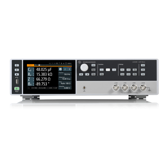
- Page 45 ® Instrument control R&S LCX Series Means of manual interaction The initial screen shows the basic parameters capacitance "C " and serial resist- ance "R ", the impendance "Z" and phase angle "Θ ". On the right, the R&S LCX displays the measurement readings.
- Page 46 ® Instrument control R&S LCX Series Means of manual interaction Figure 6-5: Example of a menu ● Selection editors Figure 6-6: Example of selection editor for measurement parameter pairs When opened, a generic label in the header of the editor window shows the parameter for selection.
-
Page 47: Accessing The Functionality
® Instrument control R&S LCX Series Means of manual interaction Figure 6-8: Alphanumeric on-screen keyboard ● Info dialogs An "Info dialog" appears when an event generates a message. The generi- cally assigned header shows the affected topic. The message describes the event, and short instructions lead you through the next steps. -
Page 48: Entering Data
® Instrument control R&S LCX Series Means of manual interaction To open the main menus To open the two main menus: 1. Press the [settings] at the front panel. 2. Select (tap) the corresponding tab on the screen. The selection leads you either to a settings parameter directly, or to a dedica- ted dialog. - Page 49 ® Instrument control R&S LCX Series Means of manual interaction For data input in dialogs, the instrument provides on-screen keypads for entering numeric and alphanumeric values. Thus, you can always set the parameters using the touchscreen, or the navigation controls at the front panel.
- Page 50 ® Instrument control R&S LCX Series Means of manual interaction 3. If the parameter does not require a unit, confirm the entered value with To enter values by using the front panel controls You can also control the R&S LCX with the front panel controls, e.g. if you have locked the touchscreen.
-
Page 51: Remote Control
® Instrument control R&S LCX Series Remote control Remote control In addition to operating the R&S LCX directly on the instrument, it is also possible to operate and control it from a remote PC. Remote control interfaces The R&S LCX provides several interfaces for remote control: ●... -
Page 52: Contacting Customer Support
® Contacting customer support R&S LCX Series Contacting customer support Technical support – where and when you need it For quick, expert help with any Rohde & Schwarz product, contact our customer support center. A team of highly qualified engineers provides support and works with you to find a solution to your query on any aspect of the operation, program- ming or applications of Rohde &... -
Page 53: Index
® Index R&S LCX Series Index IEC/IEEE ..........30 L CUR ..........29 Access L POT ..........29 Instrument ........... 47 LAN ............. 32 Active elements ........45 Trigger external ........31 Alphanumeric parameters ....... 50 USB A ........... 29, 32 Application cards ........ - Page 54 ® Index R&S LCX Series Fuses How to replace the bias fuse ....17 Kensington lock ........30 How to replace the line fuse ....18 Key ............27 ◀ ............27 ★ (User) ..........27 Getting started ......... 10 Auto ............ 28 Ground socket .........
- Page 55 ® Index R&S LCX Series Replace the line fuse How to: ..........18 Navigation controls Front panel tour ........27 Numeric data entry ........48 Safety information ........5 Numeric parameters ........ 49 Safety instructions ....... 5, 11 Security procedures .........11 Service manual ........
Need help?
Do you have a question about the LCX Series and is the answer not in the manual?
Questions and answers