Stihl TS 400 Manual
Hide thumbs
Also See for TS 400:
- Instruction manual (102 pages) ,
- Technical information (12 pages) ,
- Manual (44 pages)
Table of Contents
Advertisement
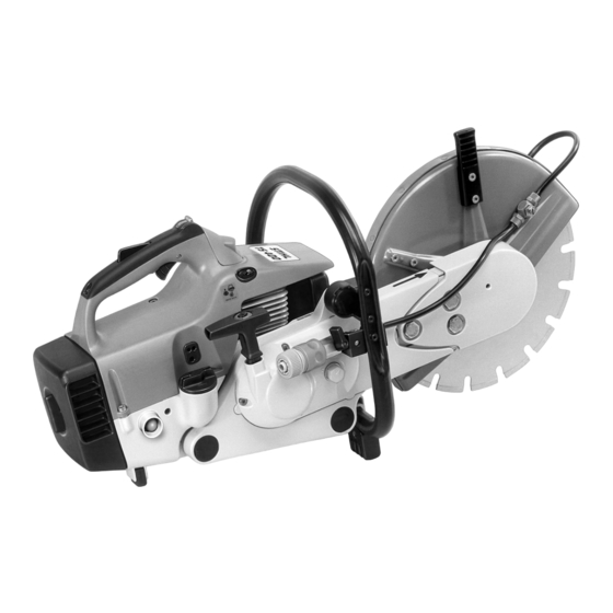
STIHL TS 400
TABLE OF CONTENTS
1.
2.
2.1
2.2
2.3
2.4
2.5
2.5.1
2.5.2
2.6
Tightening torques
3.
3.1
3.2
3.3
V-belt
3.4
3.5
4.
4.1
5.
5.1
5.2
5.2.1
5.2.2
5.2.3
pressure
5.4
5.5
5.6
5.6.1
5.6.2
5.7
5.8
5.9
5.9.1
5.9.2
6.
6.1
6.2
2
6.3
6.3.1
3
6.3.2
3
6.4
3
4
6.5
4
4
7.
4
4
7.1
7.2
5
7.2.1
6
7.2.2
7.3
6
8.
9
11
9.
11
9.1
12
9.2
13
9.3
9.4
9.5
13
10.
13
13
10.1
14
10.2
14
10.2.1
10.2.2
15
10.3
16
10.4
17
10.5
18
10.6
19
10.7
19
10.8
20
10.9
22
22
23
23
25
28
11.
28
29
11.1
30
11.2
30
30
31
32
34
34
34
34
35
35
36
37
37
38
38
38
39
39
39
41
41
41
43
44
45
45
46
47
47
STIHl
© 1995, Andreas Stihl, Waiblingen
1
50
50
52
Advertisement
Table of Contents

Related Manuals for Stihl TS 400


Summary of Contents for Stihl TS 400
-
Page 1: Table Of Contents
Exposing the cylinder 10.6 Fuel hose Cylinder and piston 10.7 Impulse hose 5.6.1 Removal 10.8 Manifold 5.6.2 Installation 10.9 Tank housing Piston rings Decompression valve Crankcase 5.9.1 Removing the crankshaft 5.9.2 Installing the crankshaft STIHl © 1995, Andreas Stihl, Waiblingen... -
Page 2: Introduction
Always use original STIHL Microfilms are more up-to-date than replacement parts. Original STIHL printed replacement parts lists! parts can be identified by the STIHL part number, the STIHl logo Faults in the cut-off machine may be and the STIHL parts symbol (. -
Page 3: Specifications
STIHL TS 400 SPECIFICATIONS STIHL single-cylinder two-stroke engine with specially Engine impregnated cylinder bore Displacement: 64.1 cm Cylinder bore: 49 mm Piston stroke: 34 mm Compression: 9.5 :1 Power output to DIN 70020: 3.2 kW (4.4 HP) Max. torque: 4.1 Nm at n = 6500 rpm Max. -
Page 4: Ignition System
STIHL TS 400 Transistor-controlled Principle: Ignition system (non-contacting) magneto ignition with integrated controller and electronic speed limitation 0.15...0.3 mm Air gap: 1.6...2.2 mm before UDC Ignition timing: at n = 8000 rpm Bosch WSR 6F or Spark plug (suppressed): NGK BPMR 7 A 0.5 mm... - Page 5 STIHL TS 400 Tightening torques DG screws are screwed into plastic and light metal parts. These screws cut a thread in the material when they are screwed in for the first time. The material is permanently deformed. The screws can then be removed at will and retightened without impairing the strength of the screw connection, provided that the specified tightening torque is maintained.
-
Page 6: Cutting Wheel Drive
STIHL TS 400 CUTTING WHEEL DRIVE Bearing with guard Check axial and radial runout, see chapter 3.2. • Lever bearing with guard out of • Lock V-belt pulley in position. V-belt. • Unscrew nut and draw V-belt pulley off shaft. - Page 7 STIHL TS 400 Important! Use pliers with shortened, rounded tips. • Draw bearing out of rubber ring. • Unscrew both screws (1) and remove with helical springs (2) and sleeves. • Remove flange. • Remove washer and rubber ring. • Press both deep groove ball bearings and the ring out of the bearing with drift pin (1).
- Page 8 STIHL TS 400 • Slide first deep groove ball bearing (1), • Place washer on bearing. • Slide on V-belt pulley with the longer, ring (2) and second deep groove ball machined-down collar first and secure bearing (3) onto the shaft.
-
Page 9: Checking Axial And 8. Radial Runout
STIHL TS 400 Checking axial and radial runout - Insert V-belt in V-belt pulley of Since changes in the shaft diameter bearing, fit guard and loosely (due to scoring, etc.) affect the radial screw in the fastening screws. runout of the cutting wheel, it is... - Page 10 STIHL TS 400 Test sequence Actual condition Possible causes Remedy Radial runout: Visual inspection, Wear marks or scoring Fastening screw loose during Replace spindle spindle (shaft) around the cutting wheel operation, wrong cutting (shaft) mount wheels used (mount dia. > 20 mm or >...
-
Page 11: V-Belt Pulley / Clutch Drum
STIHL TS 400 V-belt V-belt pulley / clutch drum • Force out ball bearing with drift - Remove bearing with guard, see - Remove V-belt, see chapter 3.3. pin (1). chapter 3.1. - Remove starter wheel, see • Unscrew the screws of the chapter 7.3. -
Page 12: Clamp
STIHL TS 400 Clamp • - Remove starter cover, • Remove the clamping lever from the Insert both parts together. Tighten see chapter 3.3. housing slot. the fastening nuts with a torque of 4.5 Nm. • Turn hexagon on clamp clockwise... -
Page 13: Clutch
STIHL TS 400 CLUTCH ENGINE Removal and installation Muffler Refer to the manual "Troubleshootings, Refer to the manual standard repairs" for troubleshooting "Troubleshooting, standard procedures. repairs" for troubleshooting procedures. - Remove V-belt, see chapter 3.4. Note: The spark arresting screen can also be replaced without removing the muffler. -
Page 14: Leakage Testing
STIHL TS 400 5.2.1 Preparatory steps Leakage testing Defective rotary shaft seals and gaskets or cracks in the castings cause leaks through which supplementary air can enter and change the composition of the fuel/air mixture taken in. Above all, this makes it very much more difficult, if not impossible, to set the correct idle speed. - Page 15 STIHL TS 400 5.2.2 Testing with excess pressure • Check that the sleeve is present in • Remove decompression valve. • Connect the pressure hose of the manifold. the tester to the nipple on the test flange. - Check that the spark plug is secure.
-
Page 16: Testing With Excess
STIHL TS 400 5.2.3 Testing with negative pressure Note: The rotary shaft seals are in - The leak must be located and the The rotary shaft seals usually fail in perfect working order if the indicated defective part replaced if the the presence of a negative pressure. -
Page 17: Rotary Shaft Seals
STIHL TS 400 Rotary shaft seals The engine need not be dismantled Ignition side: if only the rotary shaft seals are to be - Remove flywheel, replaced. see chapter 6.5. Clutch side: - Install jaws with profile 3.1 on - Remove clutch, see chapter 4.1. -
Page 18: Exposing The Cylinder
STIHL TS 400 Exposing the cylinder Check and repair the fuel supply, carburetor, air filter and ignition system before locating faults in the engine. Refer to the manual "Trouble- shooting, standard repairs" for troubleshooting procedures. - Remove muffler, see chapter 5.1. -
Page 19: Cylinder And Piston
STIHL TS 400 Cylinder and piston 5.6.1 Removal • Unscrew the screws of the air The tabs (1) on the cap must Preparatory steps are described in guide cover. engage in the guides (2) in the chapter 5.5. shroud. - Remove air guide cover. -
Page 20: Installation
STIHL TS 400 5.6.2 Installation - Remove decompression valve as described in chapter 5.8. - Check cylinder and replace if necessary. Note: The corresponding piston must also be fitted when installing a new cylinder. New cylinders are therefore only available with piston. - Page 21 STIHL TS 400 - Ensure that the piston rings are positioned correctly. - Coat the inside of the cylinder with oil and line it up in accordance with its subsequent installation position. The piston rings may break if this is not done.
-
Page 22: Piston Rings
STIHL TS 400 Piston rings Decompression valve - Remove shroud, see chapter 5.5. - Remove piston, see chapter 5.6.1. • Screw in the cylinder base screws and alternately tighten them cross- • Unscrew decompression valve - Remove piston rings from piston. -
Page 23: Crankcase
STIHL TS 400 Crankcase 5.9.1 Removing the crankshaft - Partly unscrew the spindle of - Remove clutch, see chapter 4.1. assembly tool ZS. - Remove flywheel, see chapter 6.5. Note: The spindle has a left-hand thread. - Remove cylinder and piston, see chapter 5.6.1. - Page 24 STIHL TS 400 - The deep groove ball bearings and rotary shaft seals must also be replaced when fitting a new crankshaft. • Turn the spindle of the assembly • Carefully drive the rotary shaft tool counterclockwise until the seal out of the housing half.
-
Page 25: Installing The Crankshaft
STIHL TS 400 5.9.2 Installing the crankshaft Each half of the crankcase can - Heat the housing halves to approx. be replaced separately if the 150 °C around the seats of the crankcase is defective. deep groove ball bearings. New crankcase halves are supplied... - Page 26 STIHL TS 400 • Screw the threaded sleeve (1) - To remove the assembly tool, • Screw M5x72 screws (from the onto the screw thread (2) of the unscrew the spindle counter- set of assembly tools ZS) into two crankshaft stub.
- Page 27 STIHL TS 400 Note: Remove the protruding housing gasket on the assembly face for the cylinder. - Coat the sealing lips of the rotary shaft seals with grease, see chapter 11.2. • Hold the crankshaft and remove the - Slide the rotary shaft seal over...
-
Page 28: Ignition System
STIHL TS 400 IGNITION SYSTEM Spark plug terminal Important! Great care must be - Draw spark plug terminal off exercised during troubleshooting, ignition lead. maintenance and repair work on the ignition system. The high voltages - Remove cover from ignition lead. - Page 29 - Slide cover over spark plug terminal. Note: Before turning in the ignition lead, the high-voltage output must be - Press ignition lead into holder. filled with STIHL multi-purpose grease, see 11.2. - Plug spark plug terminal onto spark plug. Caution! Graphite (Molykote) grease and silicone insulating paste must not be used.
-
Page 30: Ignition Module
STIHL TS 400 Ignition module 6.3.1 Ignition timing 6.3.2 Removal and installation Ignition in the transistor-controlled (non-contacting) magneto ignition is timed at 1.9 mm before UDC at n = 8000 rpm and cannot be adjusted. Taking into account the permissible variation in electrical control, this value may vary from 1.6 to 2.2 mm... -
Page 31: Stop Switch Lead / Ground Lead
STIHL TS 400 Stop switch lead / ground lead Note: Before screwing in the ignition lead, the high-voltage output must be filled with STIHL multi-purpose grease, see 11.2. Caution! Graphite (Molykote) grease and silicone insulating paste must not be used. -
Page 32: Flywheel
STIHL TS 400 Flywheel • Draw out the ground lead (2). • Press catch (1) down and draw Removing the flywheel: contact sleeve (2) of stop switch lead out of the mount for retainer • Press the cap in at the bottom, slide it upwards and remove it. - Page 33 STIHL TS 400 • Unscrew the fan cover screws. Note: If the flywheel cannot be Tighten spark plug with a torque of removed by hand, screw on extractor 27.5 Nm. - Remove fan cover. (1) and lightly tap against the face of the extractor.
-
Page 34: Starter
STIHL TS 400 STARTER Rewind spring General 7.2.1 Replacement Refer to the manual "Trouble- Caution! The rewind spring may pop If the starter rope can be pulled out shooting, standard repairs" for out if it is inserted without due care. -
Page 35: Tensioning
STIHL TS 400 7.2.2 Tensioning Starter wheel - Use the starter handle to keep the starter rope taut. - Let the rope rotor go and slowly pay back the starter rope so that it is rewound on the rope rotor. -
Page 36: Av Handle System
STIHL TS 400 8. AV HANDLE SYSTEM The handle and engine housings are connected by vibration-damping, ring-shaped rubber buffers. Damaged rubber buffers must always be replaced. Upper rubber buffers, clutch side: Note: See chapter 9.5 for information on replacement. • Prise rubber buffers out of cast •... -
Page 37: Throttle Control
STIHL TS 400 THROTTLE CONTROL Throttle trigger interlock, throttle trigger - Remove cap from shroud, • Remove slide control from • Remove torsion spring from see 6.5. bearing. throttle trigger. • Unscrew screw (1) in handle The parts are installed in reverse moulding (2). -
Page 38: Leaf Spring
STIHL TS 400 Leaf spring Handle - Unscrew spark plug, see 6.5. - Remove slide control, see 9.1. - Remove shroud, see 5.5. • Unscrew the screws from the handle mount. • Unscrew the screw (1) on retainer (2). - Remove retainer with rod. -
Page 39: Handle Mount
STIHL TS 400 Handle mount FUEL SYSTEM 10.1 Air filter The engine performance deteriorates, fuel consumption increases and starting is made more difficult when the filters are soiled. The air filter must be cleaned when engine performance declines. - Remove coarse dirt around the air filter. - Page 40 STIHL TS 400 Note: Auxiliary filter must be replaced immediately if flock covering is damaged. - Clean filter chamber. The parts are reassembled in reverse order. • Remove prefilter from filter cover. • Draw main filter out of filter housing.
-
Page 41: Carburetor
STIHL TS 400 10.2.2 Removal and installation 10.2 Carburetor 10.2.1 Leakage testing Refer to the manual "Trouble- shooting, standard repairs" for troubleshooting procedures. The carburetor can be tested for leaks with the aid of the carburetor / crankcase tester. - Remove shroud, see 5.5. - Page 42 STIHL TS 400 • Unscrew the screws in the filter • Remove gasket. Note: Before fitting the carburetor, base. ensure that the sleeve is present in the manifold. • Unscrew nuts. • Draw carburetor off stud bolts. Note: Refer to the "Carburetor"...
-
Page 43: Carburetor Adjustment
STIHL TS 400 10.3 Carburetor adjustment The ignition system of this cut-off machine has been equipped with an electronic maximum speed limiter. Unlike the case in machines with conventional ignition system, the maximum speed cannot be set beyond a predetermined limit by adjusting the carburetor. -
Page 44: Tank Vent
STIHL TS 400 10.4 Tank vent A pressure balance must always be maintained between the inside of the fuel tank and the atmosphere outside in order to ensure troublefree operation of the carburetor. This pressure balance is maintained by the tank vent. -
Page 45: Pick-Up Body
STIHL TS 400 10.5 Pick-up body 10.6 Fuel hose Fuel is transferred from the fuel tank to the carburetor via the fuel line by the diaphragm pump. Any impurities entering the fuel tank with the fuel are trapped by the pick-up body (filter). -
Page 46: Impulse Hose
STIHL TS 400 10.7 Impulse hose • Draw out fuel hose. - Remove carburetor, see 10.2.2. • Draw impulse hose off connector. The parts are installed in reverse • Disconnect spark plug terminal (1) order. from spark plug. • Remove ignition lead and stop switch lead from holder (2). -
Page 47: Manifold
STIHL TS 400 10.9 Tank housing 10.8 Manifold The (small) left-hand half of the housing can be replaced separately if damaged. The complete tank housing must be replaced if the (large) righthand half of the housing is damaged. - Remove crankcase, see 5.9.1. - Page 48 STIHL TS 400 • Remove that half of the housing. • Prise stoppers out of lower • Press contact spring holder out of rubber buffers. slot. - Remove holder. • Remove gasket. • Unscrew the screws in the • Remove manifold.
- Page 49 STIHL TS 400 • Pull pick-up body off fuel hose. • Prise out spout. Insert manifold so that the straight edge (1) points towards the impulse hose (2). • Lever out flange (1) of fuel hose. - Unscrew filler cap.
-
Page 50: Special Tools And Service Accessories
STIHL TS 400 Special tools and service accessories 11.1 Special tools Designation Part No. Rem. Locking strip for piston 0000 893 5903 Locking the crankshaft Sealing plate 0000 855 8106 Sealing the exhaust during leakage tests Wooden assembly block 1108 893 4800... - Page 51 STIHL TS 400 Designation Part No. Torque wrench 5910 890 0301 Screw connections (0.5 to 18 Nm) 5910 890 0302 Torque wrench 5910 890 0311 Screw connections (6 to 80 Nm) 5910 890 0312 Screwdriver QI-T27x150 5910 890 2400 For all IS screws...
-
Page 52: Service Accessories
STIHL TS 400 11.2 Service accessories Designation Part No. Rotary shaft seals Lubricant grease 0781 120 1111 Cleaning the crankshaft stub Conventional solvent-based degreasing agent without CFCs and halogenated hydrocarbons HTR ignition lead (10 m) 0000 930 2251 High-voltage output in ignition module...
Need help?
Do you have a question about the TS 400 and is the answer not in the manual?
Questions and answers