
Related Manuals for Festo Pick&Place Station


Summary of Contents for Festo Pick&Place Station
- Page 1 Station Pick&Place Handbuch Pick&Place station Manual CD-ROM included 678864 de/en 04/06 R2.2...
- Page 2 Ausbildungsunternehmens und/oder sonstiger Dritter aus, die bei Gebrauch/Einsatz der Anlage außerhalb einer reinen Ausbildungssituation auftreten; es sei denn Festo Didactic hat solche Schäden vorsätzlich oder grob fahrlässig verursacht. This station has been developed and produced solely for vocational and further training purposes in the field of automation and technology.
-
Page 3: Table Of Contents
Montage der Station ___________________________________________ 29 Sensoren justieren _____________________________________________ 30 6.3.1 Näherungsschalter (Pick&Place, Schlitteneinheiten) _________________ 30 6.3.2 Druckschalter (Pick&Place, Vakuumsauger) ________________________ 31 6.3.3 Reflex-Lichttaster (Band, Werkstücknachweis) ______________________ 32 6.3.4 Einweg-Lichtschranke (Band, Werkstücknachweis)___________________ 33 Drosselrückschlagventile einstellen _______________________________ 34 © Festo Didactic 678864... - Page 4 6.11.1 Vernetzung ___________________________________________________ 48 6.11.2 Hardwareanpassungen _________________________________________ 48 Wartung _____________________________________________________ 49 Inhalt der CD-ROM ___________________________________________________ 51 Montageanleitungen ___________________________________________ 51 Schaltpläne __________________________________________________ 51 Programmierung ______________________________________________ 51 Stücklisten ___________________________________________________ 51 Bedienungsanleitungen ________________________________________ 52 Datenblätter __________________________________________________ 52 Aktualisierungen ____________________________________________________ 53 © Festo Didactic 678864...
- Page 5 6.3.2 Pressure switch (Pick&Place, vacuum suction cup) ___________________ 81 6.3.3 Diffuse sensor (Conveyor belt, detection of workpieces) ______________ 82 6.3.4 Through-beam sensor (Conveyor belt, detection of workpieces) ________ 83 Adjusting one-way flow control valves _____________________________ 84 © Festo Didactic 678864...
- Page 6 Manual override _______________________________________________ 86 Voltage supply ________________________________________________ 86 Loading the PLC program _______________________________________ 87 6.9.1 Siemens controller _____________________________________________ 87 6.9.2 Festo controller _______________________________________________ 90 6.9.3 Allen Bradley controller _________________________________________ 92 6.9.4 Mitsubishi/MELSEC controller ___________________________________ 95 6.10 Starting the sequence __________________________________________ 97 6.11...
-
Page 7: Einleitung
Einleitung Das Lernsystem Automatisierung und Technik von Festo Didactic orientiert sich an unterschiedlichen Bildungsvoraussetzungen und beruflichen Anforderungen. Die Anlagen und Stationen des Modularen Produktions-Systems (MPS ) ermöglichen eine an der betrieblichen Realität ausgerichtete Aus- und Weiterbildung. Die Hardware setzt sich aus didaktisch aufbereiteten Industriekomponenten zusammen. -
Page 8: Lerninhalte
• Auswahl pneumatischer Komponenten Linearantriebe – Schwenkantriebe – Vakuumgeneratoren – • Sicherheit bei pneumatischem Energieausfall Vakuumspeicher – • SPS Programmierung Programmieren eines Betriebsartenteils – Programmieren des RICHTEN Ablaufs – Programmieren der NOT-AUS Funktion – • Optimieren der Zykluszeit © Festo Didactic 678864... -
Page 9: Wichtige Hinweise
Alle Personen, die mit Arbeiten am MPS beauftragt sind, verpflichten sich, vor Verpflichtung der Arbeitsbeginn: Auszubildenden • das Sicherheitskapitel und die Warnhinweise in diesem Handbuch zu lesen, • die grundlegenden Vorschriften über Arbeitssicherheit und Unfallverhütung zu beachten. © Festo Didactic 678864... -
Page 10: Gefahren Im Umgang Mit Dem Modularen Produktions-System
Produktions-System der Maschine oder an anderen Sachwerten entstehen. Das MPS ist nur zu benutzen: • für die bestimmungsgemäße Verwendung und • in sicherheitstechnisch einwandfreiem Zustand. Störungen, die die Sicherheit beeinträchtigen können, sind umgehend zu beseitigen! © Festo Didactic 678864... -
Page 11: Gewährleistung Und Haftung
Ausbildungsunternehmens und/oder sonstiger Dritter aus, die bei Gebrauch/Einsatz der Anlage außerhalb einer reinen Ausbildungssituation auftreten; es sei denn Festo Didactic hat solche Schäden vorsätzlich oder grob fahrlässig verursacht. Diese Station ist ausschließlich für die Aus- und Weiterbildung im Bereich Bestimmungsgemäße... - Page 12 1. Einleitung © Festo Didactic 678864...
-
Page 13: Sicherheitshinweise
• Entkuppeln Sie keine Schläuche unter Druck. • Seien Sie beim Einschalten der Druckluft besonders vorsichtig. Zylinder können selbsttätig aus- oder einfahren. Mechanik • Montieren Sie alle Komponenten fest auf die Platte. • Greifen Sie nur bei Stillstand in die Station. © Festo Didactic 678864... - Page 14 2. Sicherheitshinweise © Festo Didactic 678864...
-
Page 15: Technische Daten
(MO/HS) (SO) Verteilen*** (VE) Prüfen (PR) Bearbeiten (BE) Handhaben (HA) Puffern (PU) Pick&Place (PP) FluidicMuscle Presse (FP) Trennen (TR) Lagern (LA) Roboter Montieren* (MO/HS) * Montieren mit Stanzen / ** Sortieren DP / *** Verteilen AS-Interface © Festo Didactic 678864... - Page 16 3. Technische Daten © Festo Didactic 678864...
-
Page 17: Transport/Auspacken/Lieferumfang
Die Transportbox darf ausschließlich mit geeigneten Hubwagen oder Gabelstaplern transportiert werden. Die Transportbox muss gegen Umfallen und Herunterfallen gesichert sein. Transportschäden sind unverzüglich dem Spediteur und Festo Didactic zu melden. Auspacken Beim Auspacken der Station das Füllmaterial der Transportbox vorsichtig entfernen. - Page 18 4. Transport/Auspacken/Lieferumfang © Festo Didactic 678864...
-
Page 19: Aufbau Und Funktion
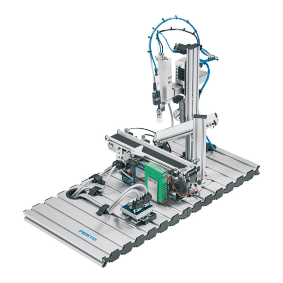
Die Aufgabe der Station Pick&Place ist es • Werkstücke (Gehäuse) transportieren • Werkstücke (Gehäuse) stoppen • Werkstückeinsätze einlegen • Komplette Werkstücke (Gehäuse und Einsatz) vereinzeln Hinweis Die Werkstückeinsätze „Uhr“, „Thermometer“ und „Hygrometer“ passen nur in die Werkstücke „Gehäuse“. © Festo Didactic 678864... - Page 20 5. Aufbau und Funktion Der Aufbau der Station Pick&Place besteht aus: • Modul Pick&Place • Modul Band • Modul Rutsche • Profilplatte • Wagen • Bedienpult • SPS-Board Station Pick&Place mit Wagen, Bedienpult und SPS Board © Festo Didactic 678864...
-
Page 21: Aufbau Als Einzelstation
Aufbau der Station Pick&Place als Einzelstation bzw. letzte Station einer Anlage Der Stopper am Ende des Bands ist montiert. 5.1.2 Aufbau mit Folgestation Aufbau der Station Pick&Place mit Folgestation Der Stopper am Ende des Bands ist demontiert. © Festo Didactic 678864... -
Page 22: Funktion
3. Ein Werkstückeinsatz wird von der Rutsche geholt und in das Gehäuse eingelegt. 4. Der Bandmotor wird eingeschaltet und der Vereinzeler lässt das Werkstück passieren. 5. Das Werkstück wird am Bandende nachgewiesen, der Bandmotor wird ausgeschaltet. © Festo Didactic 678864... -
Page 23: Modul Pick&Place
Das Modul Pick&Place ist ein pneumatisches Handlinggerät. Das Modul ist aus präzisen Schlitteneinheiten aufgebaut. Die Endlagen der Schlitten werden mit Näherungsschaltern erfasst. Ein Faltenbalg-Saugnapf erfasst die Werkstückeinsätze. Direkt an den Faltenbalg- Saugnapf ist ein Vakuumfilter montiert, damit keine Schmutzpartikel in den Vakuumgenerator gelangen. © Festo Didactic 678864... -
Page 24: Modul Band
Nachweis der Werkstücke am Bandanfang, vor dem Vereinzeler und am Bandende erfolgt durch optische Näherungsschalter mit Lichtleitern. Der Antrieb des Gurtbandes erfolgt durch einen Gleichstrom-Getriebemotor. Durch einen angebauten Elektromagneten (Drehmagnet) mit Vereinzeler können die Werkstücke gestoppt und vereinzelt werden. Die Endlagen werden mit induktiven Näherungsschaltern nachgewiesen. © Festo Didactic 678864... -
Page 25: Modul Rutsche
5. Aufbau und Funktion Modul Rutsche Das Modul Rutsche dient zum Transportieren oder Lagern der Werkstücke. Durch die variable Einstellung von Neigung und Höhe ist dieses Modul universell einsetzbar. 6 Werkstückeinsätze passen auf die Rutsche. © Festo Didactic 678864... - Page 26 5. Aufbau und Funktion © Festo Didactic 678864...
-
Page 27: Inbetriebnahme
• die montierte und justierte MPS Station • ein Bedienpult • ein SPS Board • ein Netzgerät 24 V DC, 4,5 A • eine Druckluftversorgung mit 600 kPa (6 bar), Saugleistung ca. 50 l/min • einen PC mit installierter SPS Programmiersoftware © Festo Didactic 678864... -
Page 28: Mechanischer Aufbau
6. Inbetriebnahme 6.2.1 Montage von Profilplatte und Bedienpult Mechanischer Aufbau 2 (4x) 4 (4x) 5 (2x) Profilplatte Hammermutter M6-32 (4x) Wagen Zylinderschraube M6x10 (4x) Blechschraube 3,5x9 (2x) Bedienpult © Festo Didactic 678864... -
Page 29: Montage Der Station
6. Inbetriebnahme 6.2.2 Montage der Station Hinweise zur Montage der Station entnehmen Sie bitte der Montageanleitung der Station Pick&Place im Verzeichnis Deutsch\10_PickPlace\Montageanleitungen der mitgelieferten CD-ROM. © Festo Didactic 678864... -
Page 30: Sensoren Justieren
7. Kontrollieren Sie die Positionierung des Näherungsschalters durch wiederholte Probeläufe der Schlitteneinheit (ein-/ausfahren). Dokumente • Datenblätter Näherungsschalter SME-10 (525914) im Verzeichnis Deutsch\10_PickPlace\Datenblaetter der mitgelieferten CD-ROM. • Bedienungsanleitungen Näherungsschalter SME-10 (659882) im Verzeichnis Deutsch\10_PickPlace\Bedienungsanleitungen der mitgelieferten CD-ROM. © Festo Didactic 678864... -
Page 31: Druckschalter (Pick&Place, Vakuumsauger)
Lassen Sie hierzu die Schlitteneinheiten mehrmals von Endlage zu Endlage fahren. Das Werkstück darf nicht abfallen. Dokumente • Datenblätter Druckschalter SDE5-V1 (527458) im Verzeichnis Deutsch\10_PickPlace\Datenblaetter der mitgelieferten CD-ROM. • Bedienungsanleitungen Druckschalter SDE5-V1 (662804) im Verzeichnis Deutsch\10_PickPlace\Bedienungsanleitungen der mitgelieferten CD-ROM. © Festo Didactic 678864... -
Page 32: Reflex-Lichttaster (Band, Werkstücknachweis)
Alle Werkstücke müssen sicher erkannt werden. Dokumente • Datenblätter Lichtleitergerät SOEG_L (165327) und Lichtleiter Reflex SOEZ-RT (165358) im Verzeichnis Deutsch\10_PickPlace\Datenblaetter der mitgelieferten CD-ROM. • Bedienungsanleitungen Lichtleitergerät (369669) und Lichtleiter Reflex (369682) im Verzeichnis Deutsch\10_PickPlace\Bedienungsanleitungen der mitgelieferten CD-ROM. © Festo Didactic 678864... -
Page 33: Einweg-Lichtschranke (Band, Werkstücknachweis)
5. Legen Sie ein Werkstück in den Erfassungsbereich der Lichtschranke. Die Schaltzustandsanzeige erlischt. Dokumente • Datenblätter Lichtleitergerät SOEG_L (165327) und Lichtleiter Einweg SOEZ-SE (165360) im Verzeichnis Deutsch\10_PickPlace\Datenblaetter der mitgelieferten CD-ROM. • Bedienungsanleitungen Lichtleitergerät (369669) und Lichtleiter Einweg (369684) im Verzeichnis Deutsch\10_PickPlace\Bedienungsanleitungen der mitgelieferten CD-ROM. © Festo Didactic 678864... -
Page 34: Drosselrückschlagventile Einstellen
Überprüfen Sie vor dem Start der Station: • die elektrischen Anschlüsse • den korrekten Sitz und den Zustand der Druckluftanschlüsse • die mechanischen Komponenten auf sichtbare Defekte (Risse, lose Verbindungen usw.) Beseitigen Sie entdeckte Schäden vor dem Start der Station! © Festo Didactic 678864... -
Page 35: Kabelverbindungen
Stecken Sie den Stecker XMG1 des SPS Boards in die Buchse XMG1 des Bedienpults. 6. SPS Board – Netzgerät Stecken Sie die 4 mm Sicherheitsstecker in die Buchsen des Netzgerätes. 7. PC – SPS Verbinden Sie Ihren PC durch ein Programmierkabel mit der SPS. © Festo Didactic 678864... -
Page 36: Pneumatischer Anschluss
CPV Ventilinsel (165100) im Verzeichnis Deutsch\10_PickPlace\Bedienungsanleitungen der mitgelieferten CD-ROM. • Die Stationen werden über ein Netzgerät mit 24 V Gleichspannung (max. 5 A) Spannungsversorgung versorgt. • Die Spannungsversorgung der kompletten Station erfolgt über das SPS Board. © Festo Didactic 678864... -
Page 37: Sps Programm Laden
– Sie können den Betriebsartenschalter loslassen. Er geht dabei selbsttätig in – die STOP Stellung. Die SPS ist urgelöscht und zum Laden der Programme bereit. – 6. Betriebsartenschalter in Position STOP 7. Starten Sie die Programmiersoftware © Festo Didactic 678864... - Page 38 9. Wählen Sie die entsprechende Hardwarekonfiguration und laden Sie diese in Ihre SPS: – SPS 313C – SPS 313C 2DP – SPS 314 – SPS 315 2DP 10. Wählen Sie das Projekt 10PP_AS oder 10PP_KFA (AS = Ablaufsprache, KFA = KOP/FUP/AWL) © Festo Didactic 678864...
- Page 39 6. Inbetriebnahme 11. Laden Sie das Projekt in die Steuerung Zielsystem Laden Folgen Sie den Anweisungen auf dem Bildschirm 12. Betriebsartenschalter in Position RUN © Festo Didactic 678864...
-
Page 40: Festo Steuerungen
6. Inbetriebnahme 6.9.2 Festo Steuerungen • Steuerungen: Festo FEC FC640, IPC CPU HC02, IPC CPU HC20 • Programmiersoftware: Festo FST Version 4.02 1. PC und Steuerung mit dem Programmierkabel TTL-RS232 verbinden 2. Netzgerät einschalten 3. Druckluftversorgung einschalten 4. NOT-AUS Taster entriegeln (falls vorhanden) 5. - Page 41 6. Inbetriebnahme 8. Kompilieren Sie das Projekt Projekt Alles übersetzen 9. Laden Sie das Projekt in die Steuerung Online Projekt laden Folgen Sie den Anweisungen auf dem Bildschirm © Festo Didactic 678864...
-
Page 42: Allen Bradley Steuerungen
Communications Configure Drivers… in der Liste “Available Driver Types“ die Einstellung “RS-232 DF1 devices“ wählen und auf Add New…klicken Meldung (“Choose a name…“, Vorgabe: AB_DF1-1) mit OK bestätigen Auto configure OK Close © Festo Didactic 678864... - Page 43 Processor Memory und bestätigen Sie mit OK. Wenn die COMM 0.-LED erlischt, ist der Speicher der SPS gelöscht und zum – Laden der Programme bereit. Öffnen Sie die Projektdatei 10_PP_K im Verzeichnis Quellen\ – SPS Programme\Release C\ML 1500 der mitgelieferten CD-ROM. © Festo Didactic 678864...
- Page 44 Comms. System Comms. Steuerung auswählen, auf Download klicken. Bestätigen Sie die nachfolgenden Meldungen ("Revision note","…sure to proceed with Download?", "…want to go online?") mit Ja bzw. OK 8. Betriebsartenschalter in Position REM bzw. RUN © Festo Didactic 678864...
-
Page 45: Mitsubishi/Melsec Steuerungen
SPS Programme\Release C\FX1N der mitgelieferten CD-ROM. Extras Project Restore … Projektdatei auswählen (CD ROM: Quellen\SPS Programme\Release C\FX1N) 10_PP_AS.pcd Öffnen Zielverzeichnis auswählen OK nachfolgende Meldung (“After saving,…”)mit OK bestätigen 7. Kompilieren Sie das Projekt © Festo Didactic 678864... - Page 46 6. Inbetriebnahme Project Rebuild all 8. Laden Sie das Projekt in die Steuerung Project Transfer Download to PLC… nachfolgende Meldungen ("Transfer to PLC", ….),mit OK bestätigen 9. Betriebsartenschalter in Position RUN © Festo Didactic 678864...
-
Page 47: Ablauf Starten
• Der Ablauf kann durch Drücken des NOT-AUS Tasters oder durch Drücken des STOP Tasters jederzeit unterbrochen werden. • Mit dem Schlüsselschalter AUTO/MAN können Sie zwischen Dauerzyklus (AUTO) und Einzelzyklus (MAN) wählen. • Bei einer Kombination mehrerer Stationen gilt: Richten der einzelnen Stationen erfolgt entgegen dem Materialfluss. © Festo Didactic 678864... -
Page 48: Kombination Von Stationen
Bei der Station Verteilen ist nur der StationLink Empfänger montiert. Bei der Station Sortieren ist nur der StationLink Sender montiert. 6.11.2 Hardwareanpassungen Stopper am Bandende Wird die Station Pick&Place mit einer Folgestation betrieben, muss der Stopper am Ende des Bands demontiert werden. © Festo Didactic 678864... -
Page 49: Wartung
• die Linsen der optischen Sensoren, der Faseroptiken sowie Reflektoren • die aktive Fläche des Näherungsschalters • die gesamte Station mit einem weichen, fuselfreien Tuch oder Pinsel gereinigt werden. Es dürfen keine aggressiven oder scheuernde Reinigungsmittel verwendet werden. © Festo Didactic 678864... - Page 50 7. Wartung © Festo Didactic 678864...
-
Page 51: Inhalt Der Cd-Rom
Inhalt der CD-ROM Hinweis Alle aufgelisteten Dokumente und Medien sind auf der mitgelieferten CD ROM (665871) im Verzeichnis Deutsch\10_PickPlace gespeichert. Montageanleitungen Station Pick&Place Schaltpläne Station Pick&Place, elektrisch Station Pick&Place, elektropneumatisch Programmierung GRAFCET Station Pick&Place E/A-Belegung Stücklisten Station Pick&Place © Festo Didactic 678864... -
Page 52: Bedienungsanleitungen
Schalldämpfer U-M5 004 645 Steckdose mit Anschlusskabel SIM-M8-4GD 158 960 Steckdose mit Anschlusskabel SIM-M8-3GD 159 420 Steckdose mit Anschlusskabel SIM-M8-3 WD 159 422 Steckverbindung 153 329 Steckverschraubung 186 117 Vakuumsaugdüse VN 193 552 Vakuumfilter ESF 191 203 © Festo Didactic 678864... -
Page 53: Aktualisierungen
Aktualisierungen Aktuelle Informationen und Ergänzungen zur Technischen Dokumentation der MPS Stationen finden Sie im Internet unter der Adresse: http://www.festo-didactic.de/Services > MPS © Festo Didactic 678864... - Page 54 Aktualisierungen © Festo Didactic 678864...
-
Page 55: Contents
6.3.2 Pressure switch (Pick&Place, vacuum suction cup) ___________________ 81 6.3.3 Diffuse sensor (Conveyor belt, detection of workpieces) ______________ 82 6.3.4 Through-beam sensor (Conveyor belt, detection of workpieces) ________ 83 Adjusting one-way flow control valves _____________________________ 84 © Festo Didactic 678864... - Page 56 Manual override _______________________________________________ 86 Voltage supply ________________________________________________ 86 Loading the PLC program _______________________________________ 87 6.9.1 Siemens controller _____________________________________________ 87 6.9.2 Festo controller _______________________________________________ 90 6.9.3 Allen Bradley controller _________________________________________ 92 6.9.4 Mitsubishi/MELSEC controller ___________________________________ 95 6.10 Starting the sequence __________________________________________ 97 6.11...
-
Page 57: Introduction
Introduction The Festo Didactic Learning System for Automation and Technology is designed to meet a number of different training and vocational requirements. The systems and stations of the Modular Production System (MPS ) facilitate industry-orientated vocational and further training and the hardware consists of didactically suitable industrial components. -
Page 58: Training Contents
Vacuum generators – • Safety during pneumatic power failure Vacuum reservoir – • PLC programming Programming of an operational mode – Programming of a RESET sequence – Programming of an EMERGENCY-STOP function – • Optimising cycle time © Festo Didactic 678864... -
Page 59: Important Notes
Prior to commencing work, all persons assigned to working on the MPS have a duty Duty of trainees • read the chapter on safety and the cautionary notes in this manual and, • observe the basic regulations regarding operational safety and the prevention of accidents. © Festo Didactic 678864... -
Page 60: Risks Involved In Dealing With The Modular Production System
The MPS is to be used only: • for its intended purpose and • in an absolutely safe conditions. Faults impairing safety must be rectified immediately! © Festo Didactic 678864... -
Page 61: Warranty And Liability
• Incorrectly carried out repairs • Catastrophies as a result of foreign bodies and vis major. Festo Didactic herewith rules out any liability for damage or injury to trainees, the training company and/or other third parties which may occur during the use/operation of the system other than purely in a training situation, unless such damage has been caused intentionally or due to gross negligence by Festo Didactic. - Page 62 1. Introduction © Festo Didactic 678864...
-
Page 63: Notes On Safety
• Particular care is to be taken when switching on the compressed air. Cylinders may advance or retract as soon as the compressed air is switched on. Mechanics • Securely mount all components on the plate. • No manual intervention unless the machine is at rest. © Festo Didactic 678864... - Page 64 2. Notes on safety © Festo Didactic 678864...
-
Page 65: Technical Data
(MO/HS) (SO) Distributing*** (VE) Testing (PR) Processing (BE) Handling (HA) Buffer (PU) Pick&Place (PP) FluidicMuscle Press (FP) Separating (TR) Storing (LA) Robot Assembly* (MO/HS) * Assembly with Punching / ** Sorting DP / *** Distributing AS-Interface © Festo Didactic 678864... - Page 66 3. Technical data © Festo Didactic 678864...
-
Page 67: Transport/Unpacking/Scope Of Delivery
The container must be transported on a suitable fork lift truck at all times and must be secured against tipping or falling off. The carrier and Festo Didactic are to be notified immediately of any damage caused during transport. Unpacking Carefully remove the padding material in the container box when unpacking the station. - Page 68 4. Transport/Unpacking/Scope of delivery © Festo Didactic 678864...
-
Page 69: Design And Function
• to transport workpieces (housings), • to stop workpieces (housings) • to insert workpiece inserts • to separate out complete workpieces (housing and insert) Note The workpiece inserts „Clock“, „Thermometer“ and „Hygrometer“ fits only to the workpiece „Housing“. © Festo Didactic 678864... - Page 70 The Pick&Place station consists of the following: • Pick&Place module • Conveyor belt module • Slide module • Profile plate • Trolley • Control console • PLC board Pick&Place station with trolley, control console and PLC board © Festo Didactic 678864...
-
Page 71: Set-Up As Individual Station
A stopper is fitted at the end of the conveyor belt. 5.1.2 Set-up with downstream station Set-up of the Pick&Place station with a downstream station The stopper at the end of the conveyor belt is removed. © Festo Didactic 678864... -
Page 72: Function
3. A workpiece insert is picked up at the slide an inserted into the housing. 4. The separator is reversed and the conveyor belt motor is switched on. 5. The complete workpiece is detected at the end of the conveyor belt. The conveyor belt motor is switched off © Festo Didactic 678864... -
Page 73: Pick&Place Module
End positions of the slides are sensed electrically via proximity sensors. A bellows suction cup picks up the workpiece inserts. Directly to the bellows suction cup a vacuum filter is mounted to prevent dirt particles to reach the vacuum generator. © Festo Didactic 678864... -
Page 74: Conveyor Belt Module
The conveyor belt is driven by a DC gear motor. Outgoing workpieces can be stopped or separated out by means of a solenoid- actuated separator. End position sensing of the separator is effected by means of inductive sensors. © Festo Didactic 678864... -
Page 75: Slide Module
Slide module The Slide module is used to transport or store the workpieces. This module can be applied universally thanks to its variably adjustable inclination and height. 6 workpiece inserts can be accommodated on the slide. © Festo Didactic 678864... - Page 76 5. Design and function © Festo Didactic 678864...
-
Page 77: Commissioning
• A PLC board • A power supply unit 24 V DC, 4.5 A • A compressed air supply of 6 bar (600 kPa), approx. suction capacity of 50 l/min • A PC with installed PLC programming software © Festo Didactic 678864... -
Page 78: Mechanical Set Up
6. Commissioning 6.2.1 Assembling profile plate and control console Mechanical set up 2 (4x) 4 (4x) 5 (2x) Profile plate T-head nut M6 x-32 (4x) Trolley Socket head screw M6x10 (4x) Screw 3.5x9 (2x) Control console © Festo Didactic 678864... -
Page 79: Assembling The Station
6. Commissioning 6.2.2 Assembling the station Instructions on assembling the station please find in the assembly instructions of the Pick&Place station in the directory English\10_PickPlace\Assembly instructions on the CD-ROM supplied. © Festo Didactic 678864... -
Page 80: Adjust Sensors
(advance/retract mini slide). Documents • Data sheets Proximity sensor SME-10 (525914) in the directory English\10_Pick&Place\Data sheets on the CD-ROM supplied. • Operating instructions Proximity sensor SME-10 (659882) in the directory English\10_Pick&Place\Operating instructions on the CD-ROM supplied. © Festo Didactic 678864... -
Page 81: Pressure Switch (Pick&Place, Vacuum Suction Cup)
The workpiece should not drop down. Documents • Data sheets Pressure switch SDE5-V1 (527458) in the directory English\10_Pick&Place\Data sheets on the CD-ROM supplied. • Operating instructions Pressure switch SDE5-V1 (662804) in the directory English\10_Pick&Place\Operating instructions on the CD-ROM supplied. © Festo Didactic 678864... -
Page 82: Diffuse Sensor (Conveyor Belt, Detection Of Workpieces)
Fibre optic device SOEG_L (165327) and fibre optic cable diffuse SOEZ-RT (165358) in the directory English\10_Pick&Place\Data sheets on the CD-ROM supplied. • Operating instructions Fibre optic device (369669) and fibre optic cable diffuse (369682) in the directory English\10_Pick&Place\Operating instructions on the CD-ROM supplied. © Festo Didactic 678864... -
Page 83: Through-Beam Sensor (Conveyor Belt, Detection Of Workpieces)
Fibre optic device (150857) and fibre optic cable through-beam (165360) in the directory English\10_Pick&Place\Data sheets on the CD-ROM supplied. • Operating instructions Fibre optic device (369669) and fibre optic cable through-beam (369684) in the directory English\10_Pick&Place\Operating instructions on the CD-ROM supplied. © Festo Didactic 678864... -
Page 84: Adjusting One-Way Flow Control Valves
• The electrical connections • The correct installation and condition of the compressed air connections • The mechanical components for visual defects (tears, loose connections etc.) Eliminate any damage detected prior to starting up the station! © Festo Didactic 678864... -
Page 85: Cable Connections
3. PLC board – power supply unit Plug the 4 mm safety plugs into the sockets of the power supply unit. 4. PC – PLC Connect your PC to the PLC by means of a programming cable. © Festo Didactic 678864... -
Page 86: Pneumatic Connection
CD-ROM supplied. • The stations are supplied with 24 V DC voltage (max. 5 A) via a power supply Voltage supply unit. • The voltage supply of the complete station is effected via the PLC board. © Festo Didactic 678864... -
Page 87: Loading The Plc Program
You can let go of the mode selector switch. – When the STOP LED comes on permanently the memory reset is completed. – The PLC is ready for program download. – 6. Mode selector switch in STOP position 7. Start the PLC programming software © Festo Didactic 678864... - Page 88 9. Select the hardware configuration and download it to the controller: – PLC 313C – PLC 313C 2DP – PLC 314 – PLC 315 2DP 10. Select the project 10PP_AS or 10PP_KFA (AS = sequential function chart, KFA = Ladder diagram/Function block diagram/Instruction list) © Festo Didactic 678864...
- Page 89 6. Commissioning 11. Download the project to the controller PLC Download Follow the instructions on the screen 12. Turn the mode selector switch of the CPU to RUN position © Festo Didactic 678864...
-
Page 90: Festo Controller
6. Commissioning 6.9.2 Festo controller • Controller: Festo FEC FC640, IPC CPU HC02, IPC CPU HC20 • Programming software: Festo FST Version 4.02 1. Connect PC and PLC using the TTL-RS232 programming cable 2. Switch on power supply unit 3. Switch on the compressed air supply 4. - Page 91 6. Commissioning 8. Compile the project Project Build Project 9. Download the project to the controller Online Download Project Follow the instructions on the screen © Festo Didactic 678864...
-
Page 92: Allen Bradley Controller
Communications Configure Drivers… select the setting “RS-232 DF1 devices“ from the list “Available Driver Types“ and click Add New… confirm note (“Choose a name…“, default: AB_DF1-1) with OK Auto configure OK Close © Festo Didactic 678864... - Page 93 When the COMM 0.- LED stops blinking the memory reset is completed. – The PLC is ready for program download. – Open the file 10_PP_K from the directory Sources\PLC Programs\Release C\ ML 1500 of the CD-ROM supplied © Festo Didactic 678864...
- Page 94 Comms. System Comms. select controller, click Download Confirm the following notes (“Revision note","…sure to proceed with Download?", "…want to go online?") with Yes or OK 8. Turn the mode selector switch of the CPU to RUN position © Festo Didactic 678864...
-
Page 95: Mitsubishi/Melsec Controller
Extras Project Restore … select a project file (CD ROM: Sources\PLC Programs\Release C\FX1N) 10_PP_AS.pcd Open Select destination directory OK Confirm the following note (“After saving,…”) with OK 7. Compile the project © Festo Didactic 678864... - Page 96 8. Download the project to the controller Project Transfer Download to PLC… Confirm the following notes ("Transfer to PLC", ….) with OK 9. Turn the mode selector switch of the CPU to RUN position © Festo Didactic 678864...
-
Page 97: Starting The Sequence
• With the key-operated switch AUTO/MAN, you can select either the continuous cycle (AUTO) or individual cycle (MAN). • The following applies in the case of a combination of several stations: The individual stations are reset against the material flow. © Festo Didactic 678864... -
Page 98: Combination Of Stations
Sorting station only the StationLink transmitter. 6.11.2 Hardware modifications Modification of the conveyor belt If the Pick&Place station is operated in combination with a downstream station, remove the mechanical stopper at the end of the conveyor belt. © Festo Didactic 678864... -
Page 99: Maintenance
• The lenses of the optical sensors, the fibre-optics and reflectors • The active surface of the proximity sensor • The entire station Do not use aggressive or abrasive cleaning agents. © Festo Didactic 678864... - Page 100 7. Maintenance © Festo Didactic 678864...
-
Page 101: Content Of The Cd-Rom
All documents and media listed below are stored in the directory English\10_Pick&Place on the CD-ROM (665871) supplied. Assembly instructions Pick&Place station Circuit diagrams Pick&Place station, electrical Pick&Place station, electropneumatic Programming GRAFCET Pick&Place station I/O allocation list Parts lists Pick&Place station © Festo Didactic 678864... -
Page 102: Operating Instructions
159 422 Starting current limiter 150 768 Start-up valve with filter control valve 152 894 Through-beam sensor, receiver 165 323 Through-beam sensor, transmitter 165 353 Vacuum generator VN 193 552 Vacuum suction cup ESS 189 401 © Festo Didactic 678864... -
Page 103: Updates
Updates Up-to-date information and additional documents for the Technical documentation of the MPS stations please find at the address: http://www.festo-didactic.de/Services > MPS © Festo Didactic 678864... - Page 104 Updates © Festo Didactic 678864...
Need help?
Do you have a question about the Pick&Place Station and is the answer not in the manual?
Questions and answers